Why I²C is one of the most commonly used communication protocols in embedded systems?
 1. Background and Importance of I²C Communication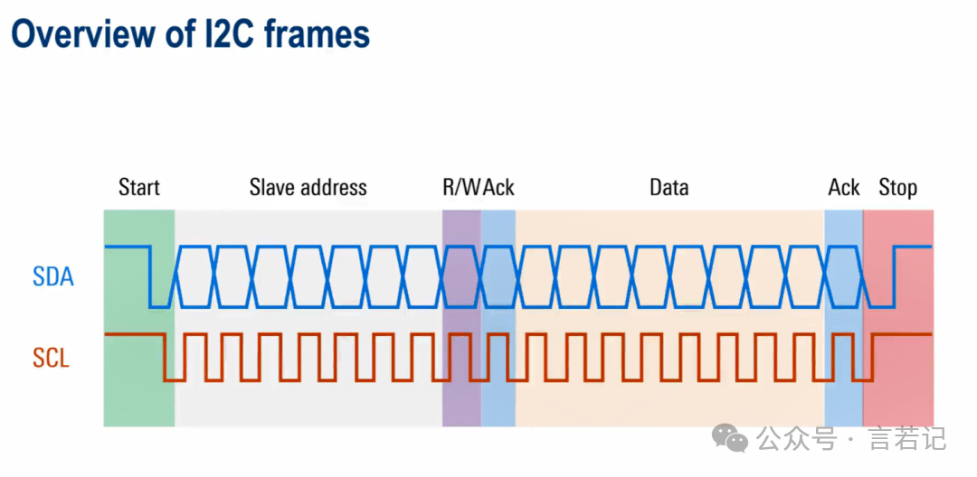
The I²C (Inter-Integrated Circuit) communication protocol was developed in the 1980s by Philips (now NXP Semiconductors) to simplify communication between various integrated circuits within electronic devices. It is particularly suitable for scenarios requiring low-speed interconnection of multiple devices, such as home appliances, consumer electronics, automotive electronics, and medical devices. The I²C protocol has become a standard communication method in embedded systems due to its simplicity, flexibility, and efficiency.
1
Widespread Applications of I²C
The I²C protocol greatly simplifies hardware design by connecting multiple devices with just two signal lines (SDA data line and SCL clock line). Therefore, it is widely used in embedded systems, especially for communication between devices such as sensors, displays, memory, keyboards, and LCD display modules. Whether it is a temperature sensor, accelerometer, or real-time clock module, these devices can achieve reliable data exchange between the master and slave devices through I²C..
2
Importance in Embedded Systems
In embedded system design, I²C provides a cost-effective solution. Since it only requires two lines, it saves pins and wiring, which is particularly useful when the number of microcontroller pins is limited. I²C also supports multiple slave devices connected to a single master device, significantly enhancing the system’s flexibility and scalability. For example, in a smartphone, I²C can simultaneously control sensors, touch screens, and camera modules..
3
Uniqueness of I²C
I²C has several significant advantages over other communication protocols (such as SPI or UART). First, its multi-master architecture supports communication between up to 127 devices on the same bus, allowing for flexible expansion. Additionally, I²C’s clock synchronization and arbitration mechanisms ensure that multiple devices can communicate on the bus without conflicts, which is crucial in complex systems. Finally, the low implementation cost, simple protocol, and ease of debugging make I²C an ideal choice for small to medium-sized embedded system designs..
 2. Basic Concepts of I²C Communication
Basic Working Principle of Communication
I²C communication relies on a master-slave architecture, meaning the master device controls the bus and initiates communication with the slave devices. The slave devices respond upon receiving requests from the master device. All data is transmitted via the SDA line, while the SCL line is used to synchronize the communication process between the master and slave devices..
I²C transmits data serially, meaning that data is sent bit by bit, with only one bit transmitted at a time. Although this method is slower, it greatly simplifies hardware design and wiring due to the use of only two lines.
Working Mechanism of Clock and Data Lines
The SCL clock line of I²C is used to synchronize communication between the master and slave devices. The master device controls the high and low levels of the SCL line to synchronize data transmission and reception, while the actual data is transmitted on the SDA line. Each time the SCL line transitions from low to high, the master or slave device sends or receives data on the SDA line. This method of synchronizing data transmission with clock signals ensures that data can be orderly and accurately transmitted between the two devices..
Acknowledge Signal in I²C Communication
An important feature of the I²C protocol is the acknowledge signal (ACK). When the master device sends data, the slave device sends an ACK signal by pulling the SDA line low after receiving each byte, indicating successful reception of the data. Conversely, if the slave device fails to receive the data, it will return a NACK signal, notifying the master device to terminate communication..
Bus Control and Conflict Avoidance
I²C allows for multiple master devices, but conflicts may arise when two master devices attempt to communicate simultaneously. To address this issue, I²C employs a bus arbitration mechanism. During communication, if two master devices try to control the bus simultaneously, the device with the higher priority (usually based on the bit value of the data being sent) will gain control of the bus, while the other device must wait..
3. Structure of the I²C Bus
Master-Slave Architecture of I²C
The I²C bus adopts a master-slave architecture, where the master device is responsible for controlling the timing of communication and initiates data exchange with the slave devices. Each slave device has a unique address, and the master device selects which slave device to communicate with by sending that address. Through this architecture, I²C can support multiple devices sharing the same bus, requiring only two lines for communication: SDA (data line) and SCL (clock line).
In this architecture, the master device has control of the bus and decides when to start or end communication. I²C supports multiple master devices, meaning multiple master devices can be connected to the same bus, but only one master device can control communication at any given time. If multiple master devices attempt to send data simultaneously, I²C uses the bus arbitration mechanism to determine which master device has priority in controlling the bus..
Unique Address of Slave Devices
I²C uses a 7-bit or 10-bit address to uniquely identify each slave device. The common 7-bit address can support up to 128 devices connected to the same bus, while the 10-bit address allows for more devices. This unique addressing system ensures that the master device can accurately select the slave device it needs to communicate with, without confusion with other slave devices.。
When the master device wants to communicate with a specific slave device, it first sends the address of that slave device and then waits for a response. If the slave device receives the address and confirms that it is ready to communicate, it will send an acknowledge signal (ACK). If the address does not match or the slave device is not ready to communicate, it will not send an acknowledge signal (NACK), and the master device will stop communication.。
Flexibility of Multi-Master Multi-Slave Architecture
I²C supports a multi-master multi-slave architecture, allowing multiple master and slave devices to coexist on the same bus. Each slave device has its own unique address, and the master device selects which specific slave device to communicate with through that address. The advantage of this architecture is that the master device does not need to lay separate communication lines for each slave device but can communicate with all slave devices through shared SDA and SCL lines.。
For the multi-master architecture, the I²C protocol uses clock synchronization and arbitration mechanisms to prevent conflicts when multiple master devices attempt to send data simultaneously. When two master devices try to initiate communication at the same time, they will determine who has higher priority by comparing the bit values of the data they are sending. The lower-priority master device will automatically stop communication and wait until the bus is free to retry.。
Role of Pull-Up Resistors on the Bus
The SDA and SCL lines of the I²C bus are both open-drain outputs, meaning devices indicate a logic low by pulling the line low, rather than driving the line high directly. Therefore, I²C systems require pull-up resistors on the SDA and SCL lines to ensure that the bus is in a logic high state when no device is pulling the line low. These pull-up resistors are crucial for ensuring the stability of the I²C bus, especially when multiple devices share the bus.
4. Data Transmission Process of I²C
Start Condition
I²C communication begins with a start condition sent by the master device. When the master device wishes to establish communication with a slave device, it pulls the SDA line from high to low while the SCL line is high. This transition is the “start condition,” notifying all slave devices on the bus that the master device is about to initiate communication.。
Address Transmission
After the start condition, the master device sends the slave device address. On the I²C bus, all slave devices have a unique 7-bit or 10-bit address. The master device selects the target device for communication by sending the slave device address. Following this, a read/write bit (R/W bit) is sent, indicating whether the master device intends to send data to the slave device (write operation) or read data from the slave device (read operation).
When the slave device receives its address, if the master device’s request matches its address, it will respond with an acknowledge signal (ACK), indicating it is ready to accept or send data. If the address does not match or the slave device is not ready, it will return a non-acknowledge signal (NACK), and the master device will stop communication or choose to retry.。
Data Transmission
Once the address is acknowledged, the data transmission between the master and slave devices begins. Data is transmitted via the SDA line, with 8 bits (one byte) transmitted at a time. I²C transmission is serial, with data sent bit by bit. After sending each byte, the receiver (whether the master or slave device) sends back an ACK signal, indicating that the data has been successfully received. If the data transmission fails, a NACK signal is returned, notifying that communication has been terminated.。
Stop Condition
After all data transmission is complete, the master device ends communication by sending a stop condition. The stop condition is the opposite of the start condition: when the SCL line is high, the master device pulls the SDA line from low back to high. At this point, the bus returns to an idle state, allowing other devices to attempt to initiate communication.。
5. Advantages and Disadvantages of I²C
Advantages
-
Pin and Wiring Savings: I²C requires only two lines for multi-device communication, greatly simplifying hardware design.。
-
Multi-Device Support: Supports up to 127 slave devices, each with a unique address, and allows for multi-master multi-slave architecture.。
-
Clock Synchronization and Acknowledge Mechanism: Ensures reliable data transmission through the ACK/NACK mechanism and can dynamically adjust communication speed based on device processing speed.。
-
Multi-Master Architecture: Supports multiple master devices sharing the bus and prevents conflicts through arbitration mechanisms.。
Disadvantages
-
Lower Speed: Standard mode only supports 100 kbps, making it unsuitable for high data volume applications.。
-
Limited Communication Distance: Suitable only for short-distance communication; distances exceeding a few meters may lead to signal degradation.。
-
Electromagnetic Interference Sensitivity: Sensitive to noise and easily affected by external interference.。
6. Comparison of I²C and CAN Communication
Number of Communication Lines
-
I²C: Requires two lines, SDA (data line) and SCL (clock line). Although the number of lines is small, it may be limited when sharing the bus.。
-
CAN: Also uses two lines, CANH and CANL, but the CAN protocol has stronger anti-interference capabilities and can achieve long-distance communication.。
2. Transmission Speed
-
I²C: Standard mode transmission speed is 100 kbps, fast mode is 400 kbps, and can reach up to 3.4 Mbps.。
-
CAN: Typical transmission speed is 1 Mbps, more suitable for applications requiring high real-time performance and reliability.。
3. Communication Distance
-
I²C: Suitable for short-distance communication, typically only applicable within a few meters.。
-
CAN: Suitable for long-distance communication, typically supporting distances from several hundred meters to 1 kilometer, and maintaining stability in noisy environments.。
4. Anti-Interference Capability
-
I²C: Sensitive to electromagnetic interference, relies on pull-up resistors, and may be unstable in noisy environments.。
-
CAN: Designed with strong anti-interference capabilities, especially suitable for noisy automotive and industrial environments.。
5. Multi-Master/Slave Support
-
I²C: Supports multi-master multi-slave communication, but the priority between devices needs to be determined through the bus arbitration mechanism, and the master device has weaker control.。
-
CAN: Multi-master architecture, using priority mechanisms to determine which device sends data, ensuring critical data is transmitted first.。
6. Application Scenarios
-
I²C: Widely used in low-speed communication scenarios involving short distances and multiple devices, such as sensors and memory in embedded devices.。
-
CAN: Suitable for scenarios requiring high reliability and real-time performance, such as automotive, industrial automation, and medical devices.。
 END
END

Scan to Follow Us