Hello everyone, many friends have previously said, “I heard that I2C is very important, but I always struggle with the timing part.” Today, we will thoroughly explain I2C from the basics to practical applications, especially focusing on the timing analysis examples, ensuring you can get hands-on after reading!
1. What is I2C? First, understand “what it is”
I2C (Inter-Integrated Circuit), known in Chinese as “集成电路间总线”, is a short-distance, low-speed serial communication protocol developed by Philips (now NXP) in 1982.
Why has it been popular for over 40 years? The core reason is “fewer wires”—it only requires 2 wires to enable communication between multiple devices, greatly simplifying circuit board design(imagine if each device had to be wired separately, the motherboard would be a mess). The sensors we commonly use (such as temperature and humidity sensors like SHT30), real-time clocks (RTC like DS3231), and EEPROM storage chips almost all use I2C communication, making it a “universal small bus” in electronic devices.
2. The physical foundation of I2C: Two wires support a whole world
To understand timing, you first need to know the “hardware foundation” of I2C—just 2 wires + pull-up resistors, simple enough to be unbelievable?
1. Hardware composition: SDA and SCL are the core
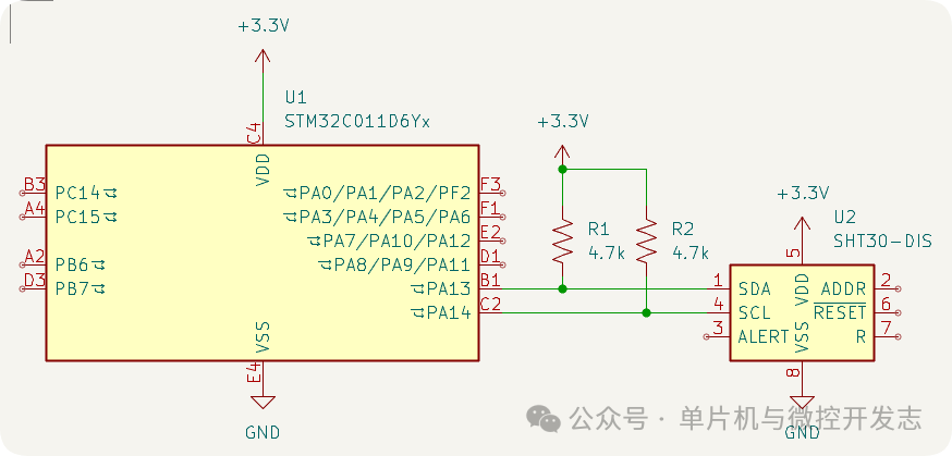
Looking directly at the hardware connection diagram, you can understand at a glance:
-
SDA (Serial Data): Data line, responsible for transmitting actual data (such as the temperature value measured by the sensor);
-
SCL (Serial Clock): Clock line, responsible for synchronizing communication rhythm (equivalent to “keeping the beat”, the master sends commands according to the beat, and the slave listens according to the beat);
-
Pull-up resistors: Typically chosen as 4.7kΩ or 10kΩ, their role is to keep SDA and SCL at a default “high level” (this knowledge will be used later in timing discussions).
No matter if there is 1 master or multiple masters, 1 slave or 10 slaves, everyone shares these two wires for SDA and SCL, which is the essence of the I2C “bus”.
2. Electrical characteristics: Why is open-drain output so important?
Many beginners ask: “Why does I2C use open-drain output?” The answer is actually hidden in “bus sharing”.
The characteristic of open-drain output is:it can only pull the level low, not pull it high. When a device wants to “speak” (send a signal), it pulls SDA/SCL low; when it does not want to speak, it releases the bus, at which point the pull-up resistor pulls the line back to high.
For example: if two devices want to send signals simultaneously, one wants to pull low, and the other wants to pull high (which would happen with push-pull output), it would cause a “short circuit”; but under open-drain output, everyone can only pull low, and even if they pull low simultaneously, the bus remains low without burning the chip—this is the key to I2C’s ability to “share the bus among multiple devices”.
3. I2C’s working mode: Who is the “conductor”?
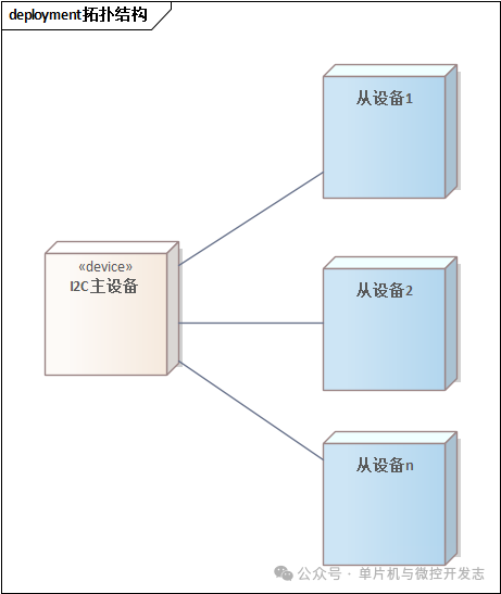
I2C adopts a “master-slave architecture”, simply put, it is “one conductor (master), multiple executors (slaves)”.
1. Master-slave architecture: Clear division of labor without confusion
-
Master: Responsible for initiating communication (for example, “Hey, temperature sensor, send me the data”), controlling the clock rhythm, and ending communication; common masters are microcontrollers (like STM32, Arduino);
-
Slave: Responsible for responding to the master’s commands (for example, “Received, here is the temperature data”), cannot actively send signals; common slaves are sensors, RTCs, etc.
To put it simply: the master is like a restaurant waiter, actively asking, “What dish do you want (command)?”; the slave is like a customer, only responding when asked, “I want sweet and sour pork (data).”
2. Multiple masters and slaves: What to do when “talking over each other”?
If there are multiple masters (for example, two microcontrollers) trying to control the bus simultaneously, there will be “talking over each other”, and “bus arbitration” is needed to resolve this.
The arbitration rule is simple:whoever pulls SDA low first wins. The specific process is:
a. Both masters initiate communication simultaneously, both start pulling SCL low;
b. After releasing SCL, both masters start sending data to SDA;
c. If master A sends “low level” and master B sends “high level”, SDA is actually “low” (because of open-drain output, as long as one pulls low, it is low);
d. Master B finds that it sent “high”, but SDA is actually “low”, realizing “someone sent before me”, and thus actively exits, allowing master A to continue controlling the bus.
The entire process has no conflict, just like two people talking at the same time, whoever’s voice is louder (pulls SDA low first) continues to speak, and the other automatically stops.
4. I2C’s data transmission: The core timing is here! (Including examples)
This part is crucial! We will take the example of “the master writing 1 byte of data to the slave” and break down the complete timing from “start” to “stop”, with timing diagrams for each stage to ensure you can understand.
First, clarify two prerequisites:
-
Data transmission is in “bytes” (1 byte = 8 bits), andthe high bit (MSB) is first (for example, to transmit 0x53 (0b01010011), first transmit bit 7 “0”, then bit 6 “1”, and finally bit 0 “1”);
-
For each byte transmitted (8 bits), the receiver must return 1 “acknowledgment bit (ACK)” to indicate “I received it, continue transmitting”.
Key Timing 1: Start Condition (S) — “Communication has started!”
The start condition is the “starting gun” for the master to initiate communication, and the timing requirements are very strict:
-
Condition: During SCL being high, SDA must transition from high to low (i.e., “high→low transition”); as shown in the diagram below.
-
Function: It tells all slaves, “Attention! I am about to send a command, everyone listen carefully”.
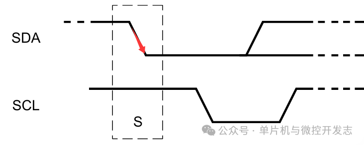
⚠️ Note: If SDA transitions while SCL is low, it does not count as a start condition, and the slave will not respond.
Key Timing 2: Address Transmission — “Who am I calling?”
After the start, the master must first transmit the “slave address”, telling the “specific slave”: “I am talking to you, others do not need to respond”.
I2C has two address modes: 7-bit address (most commonly used) and 10-bit address (used in scenarios with many devices), here we take the 7-bit address as an example.
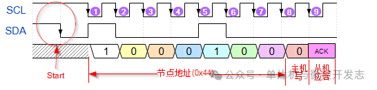
The address frame consists of 8 bits: the first 7 bits are the “slave address” (for example, the default address of SHT30 is 0x44), and the 8th bit is the “read/write bit” (0 = write, 1 = read).
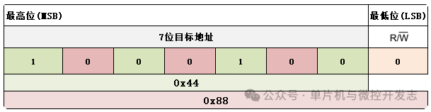
⚠️ Common mistake: The target address, such as 0x44, is placed in the high 7 bits, equivalent to shifting left by 1 bit, combined with the least significant bit of R/W to form a complete byte. This byte’s value will differ based on read or write operations. For example: during write command, it is 0x88, while during read command, it is 0x89.
The timing process:
-
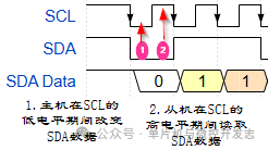
The master pulls SCL low, then during the low level of SCL, puts the first bit (high bit) of the address on SDA;
-
The master releases SCL (SCL goes high), and the slave reads the data on SDA during the high level of SCL (because the data is stable when high);
-
Repeat steps 1-2 until the first 8 bits (7 bits address + 1 bit read/write bit) are transmitted;
-
The 9th bit is the acknowledgment bit: the master releases SDA, and the slave pulls SDA low (indicating “I received the address, it is calling me”), and the master detects SDA low to confirm “the slave has responded”.
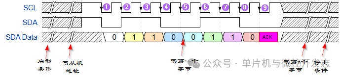
See the timing diagram below for a clear understanding.
⚠️ Small knowledge: If there is no slave response (for example, if the address is wrong), SDA will remain high, and the master will know “communication failed” and will initiate a stop condition.
Key Timing 3: Data Transmission — “This is the data to be written!”
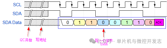
After the address confirmation, we enter the data transmission phase, taking the example of “the master writing 1 byte of data (for example, 0x66) to the slave”.
The timing process is similar to address transmission, also consisting of “8 bits of data + 1 acknowledgment bit”:
-
The master pulls SCL low, during the low level of SCL, puts the first bit (high bit, 0x66’s high bit is 0) on SDA;
-
The master releases SCL (goes high), and the slave reads the data on SDA during the high level of SCL;
-
Repeat steps 1-2 to transmit 8 bits of data (the binary of 0x66 is 01100110, transmitting 0→1→1→0→0→1→1→0 in sequence);
-
The 9th acknowledgment bit: the slave pulls SDA low (indicating “data received”), and the master detects ACK to prepare for the next step.
⚠️ Note: For each byte transmitted, there must be 1 ACK bit, regardless of whether it is an address or data.
Key Timing 4: Stop Condition (P) — “Communication has ended!”
After data transmission is complete, the master needs to initiate a “stop condition” to inform all slaves “communication has ended, the bus can be used”.
The timing requirements for the stop condition are:
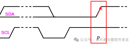
-
Condition: During SCL being high, SDA must transition from low to high (i.e., “low→high transition”);
-
Function: Marks the formal end of communication, allowing the slave to return to “waiting for commands” state.
The complete timing example: the entire process of the master writing data
Connecting the above 4 stages gives the complete timing of “start→address→data→stop”, which we display in a diagram:
Let’s walk through the timing diagram:
-
The master sends the start condition S, all slaves pay attention;
-
The master transmits the slave address (e.g., 0x44) + write bit (0), totaling 8 bits;
-
The target slave returns ACK, and the master confirms “called correctly”;
-
The master transmits data 0x66 (8 bits);
-
The slave returns ACK, and the master confirms “data received”;
-
Continue writing the remaining bytes of data (same as steps 4 and 5);
-
The master sends the stop condition P, communication ends.
Isn’t it very clear? If it is “the master reading data from the slave”, the process is similar, just set the “read/write bit” to 1, and the data is transmitted from the slave to the master, with ACK sent by the master (indicating “I received the data”).
5. I2C’s application scenarios: Where can it be used?
After learning the principles, let’s look at practical applications, and you will find I2C is everywhere:
-
Sensor interfaces: Temperature and humidity sensors (SHT30), light sensors (BH1750), accelerometers (ADXL345), almost all use I2C interfaces because it only requires 2 wires, saving space;
-
Real-time clocks (RTC): For example, DS3231, used to provide time for devices (like electronic clocks, attendance machines), communicates with the master via I2C, with low power consumption;
-
EEPROM storage: For example, AT24C02, used to store small amounts of data (like device parameters, passwords), non-volatile, simple I2C communication;
-
Display modules: For example, OLED displays (128×64), using I2C interface, which requires 2 fewer wires than SPI interface, suitable for small devices.
To summarize the advantages of I2C:fewer wires, low cost, supports multiple devices; the downside isslow speed (maximum speed of about 1Mbps, much slower than SPI), suitable for short-distance, low-speed scenarios.
6. Summary Review: Remember the Key Knowledge Points
-
The core of I2C is “2 wires (SDA + SCL) + pull-up resistors”, and open-drain output ensures multiple devices can share;
-
Master-slave architecture: the master controls the rhythm, the slave responds; multiple masters use arbitration to resolve conflicts;
-
Key timing: start (SCL high, SDA high→low), stop (SCL high, SDA low→high), 8 bits of data + 1 ACK bit;
-
Application scenarios: sensors, RTCs, EEPROMs, and other low-speed devices.
[Tools used in the article]:
1. Schematic tool KiCad 9.0.4 https://www.kicad.org/
2. Timing diagram tool Wavedrom https://wavedrom.com/
If you have any questions, feel free to leave a message in the comments. Click the following business card to follow this public account.