The chassis is metallic, with a screw hole in the middle, which connects to the ground. Here, a 1M resistor is connected in parallel with a 1nF capacitor to the circuit board ground. What are the benefits of this configuration?In metal chassis devices, the PCB GND (signal ground) is connected to the chassis GND (enclosure ground) throughparallel connection of a resistor and capacitor (referred to as RC grounding), which is a classic design that balanceselectrical safety,EMC performance, andsignal integrity. What are the advantages of this approach?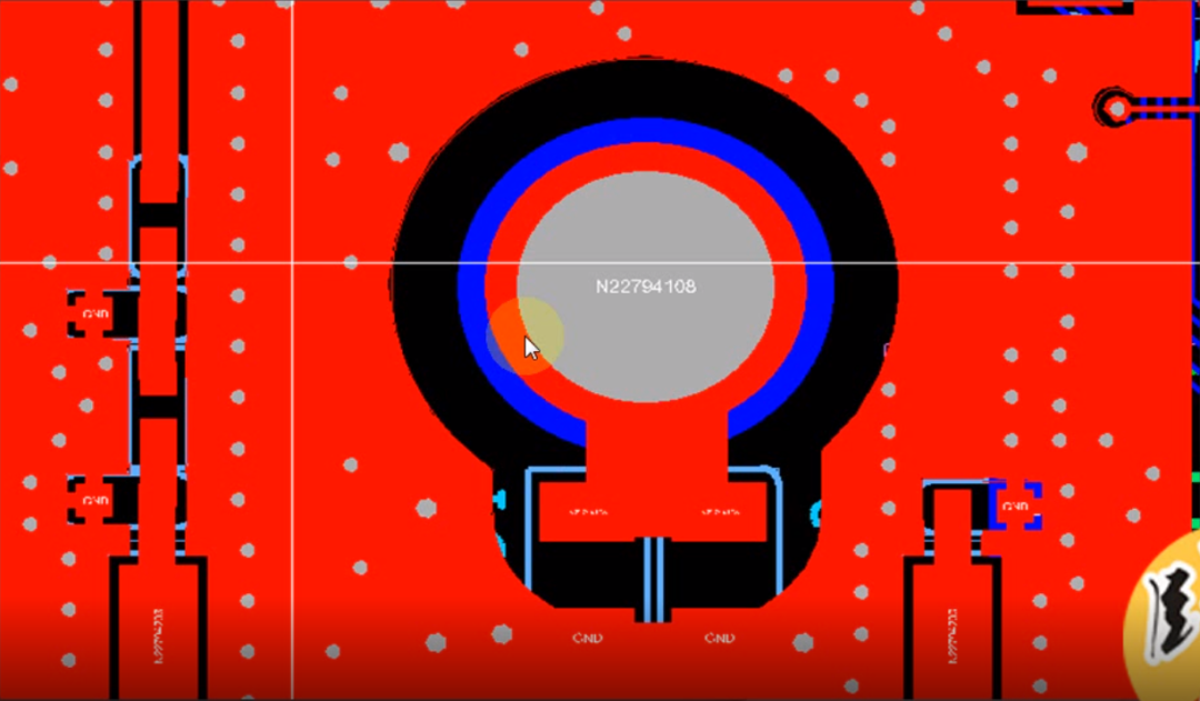
Basic Principles
1. Function of the Capacitor: High-Frequency Noise Low-Impedance Discharge
-
Bypassing High-Frequency Noise:
The metal chassis is prone to coupling external electromagnetic interference (such as RF noise and switching power supply noise). The capacitor (typically 1nF to 100nF) provides a low-impedance path for high-frequency noise, directing the interference into the chassis (Faraday cage effect), preventing it from affecting the internal circuit;
-
Suppressing EMI Radiation:
The capacitor can reduce the high-frequency noise from the circuit board leaking out through radiation or conduction, helping to pass EMC tests;
2. Function of the Resistor: Low-Frequency Isolation and Safety Current Limiting
-
Blocking Ground Loop Currents:
If the PCB GND is directly shorted to the chassis, the potential difference between different grounding points can create ground loop currents (such as 50Hz power frequency interference). The resistor (typically 1MΩ to 10MΩ) can block low-frequency loops, avoiding common-mode noise.
-
Safety Protection:
The resistor limits leakage current (such as leakage current from AC mains devices), preventing electric shock risks and meeting safety standards (e.g., IEC 60950 requires leakage current < 0.1mA).
-
If there is static electricity or high voltage outside, it can also effectively reduce the current, preventing damage to the chips inside the circuit.
3. Synergistic Effect of RC Parallel Connection
It avoids low-frequency noise introduced by ground loops (such as the “hum” in audio equipment) while not obstructing the return path of high-frequency signals. The capacitor is generally chosen to be 1nF to 100nF, and the resistor is typically 1MΩ to 10MΩ. The RC network should be as close as possible to the PCB grounding point, with short and thick capacitor leads, and the chassis grounding point should have low impedance (e.g., conductive foam).
-
At low frequencies: The resistor dominates (high impedance), blocking ground loops;
-
At high frequencies: The capacitor dominates (low impedance), discharging noise.
-
Balancing Safety and EMC: It avoids the risks of direct shorting while addressing the EMI issues caused by complete floating grounds.
Comparison with Other Grounding Solutions:
Disclaimer:This article is reproduced from the Nanshan Sweeping Monk public account. For issues related to content, copyright, and other matters, please contact the staff via WeChat (13237418207). We will respond promptly to your request for deletion!Submissions/Recruitment/Advertising/Course Cooperation/Resource Exchange, please add WeChat: 13237418207
Previous Recommendations
Key Techniques for Routing Under Transformers in High-Power Power Supply PCB Design
Complete Guide to PCB Fan Holes | These Design Details Are Easily Overlooked by Both Newbies and Veterans!
Dual Power Single Op-Amp Square Wave Oscillator Circuit
“Hardware Design: 3-Month Practical Course of Fan Yi Offline Training Project”

Scan to add customer service WeChat, note “Join Group“ to bring you into Fan Yi Education Official Technical WeChat Group, to communicate with many electronic technology experts to discuss technical questions and share insights~
Like if you enjoy it ❤️ Support “Three Links“!