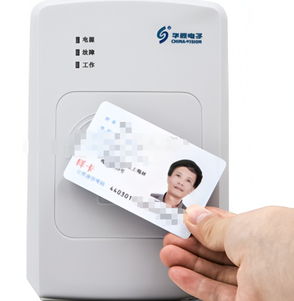
Have you seen these identity card swipe machines in many places? Today, I got one to disassemble and take a look.
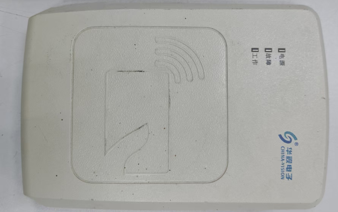
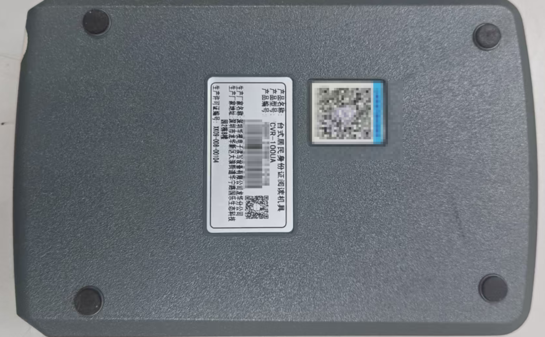
Looking at the shell, it feels like a product from 20 years ago.
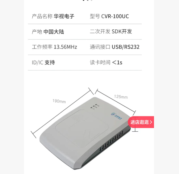
Produced by Huashi Electronics, it uses non-contact, wireless radio frequency identification (RFID). The working frequency of this wireless communication is 13.56MHz, which is because the second-generation resident identity card in China embeds a 13.56MHz non-contact IC card chip. Therefore, any device that needs to read the identity card information must operate at the same frequency to communicate and exchange data.
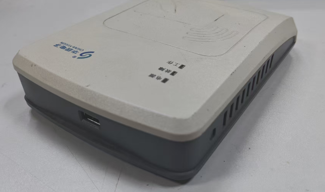
Powered by USB communication, no external power supply is needed.
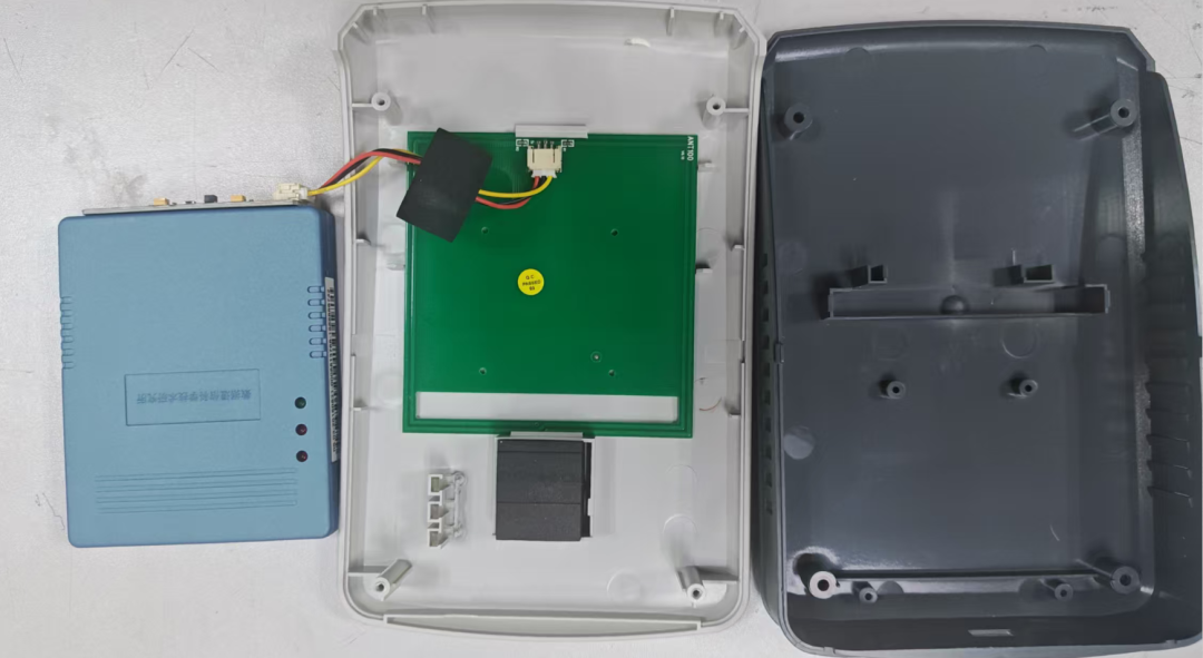
When opened, it turns out to be like this? Nested inside?
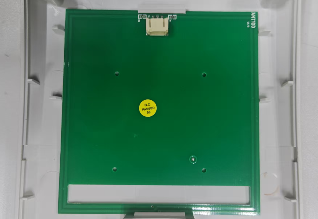
This green circuit board should be the antenna board, and the copper wire on this circuit board is designed as a circular coil. Its main function is to establish a 13.56MHz electromagnetic field energy area. Its roles are:
1. Power Supply: When the identity card is close, this electromagnetic field will wirelessly power the chip inside the identity card through electromagnetic induction (just like wireless charging), activating the chip to work.
2. Communication: At the same time, this coil is also responsible for transmitting and receiving electromagnetic wave signals carrying data, completing bidirectional data exchange between the card reader and the identity card chip.
Working Principle:
¢ The card reader continuously emits 13.56MHz radio frequency signals through the antenna.
¢ When the identity card enters the working range of the card reader’s electromagnetic field (usually within a few centimeters), the antenna inside the identity card will sense the electromagnetic field and obtain energy from it to power the chip (no battery needed).
¢ After the chip is activated, wireless data transmission occurs between the chip and the card reader at the 13.56MHz carrier frequency, completing the reading and verification of identity information.
|
|
|
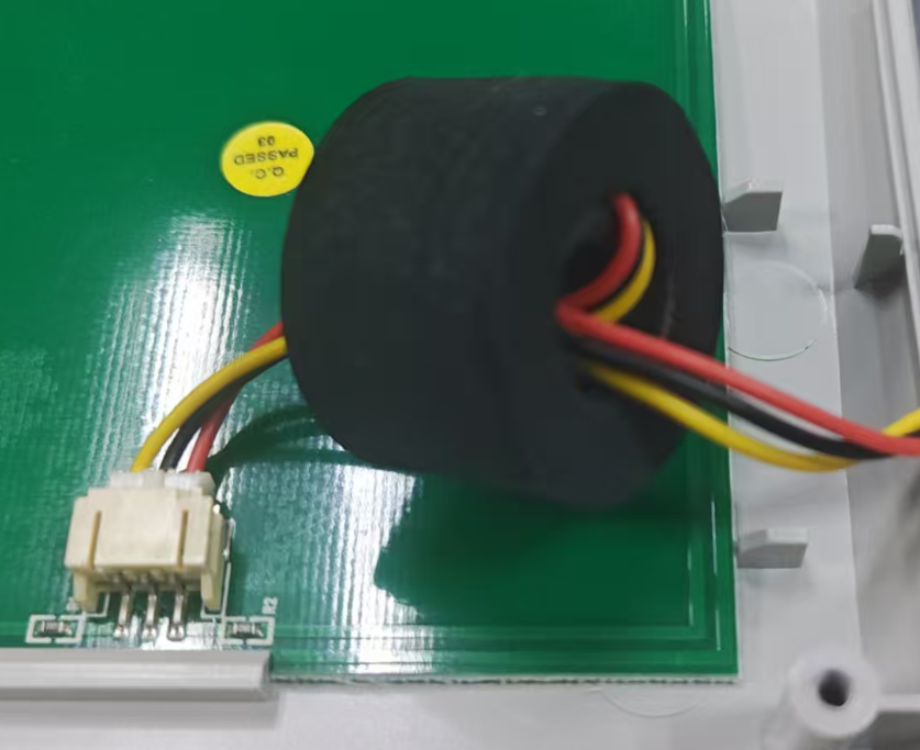
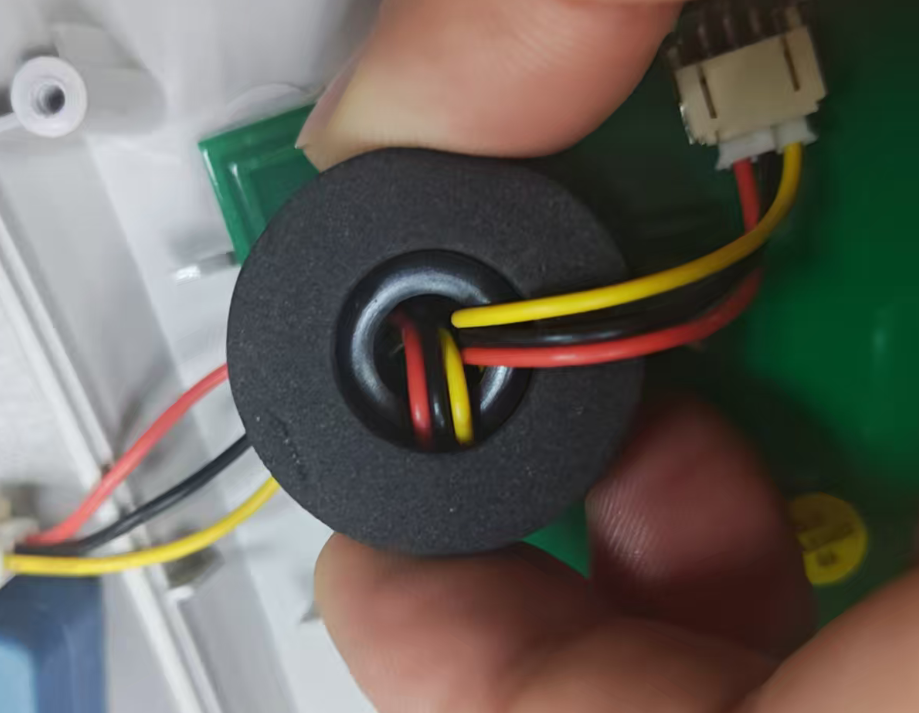
This is a large magnetic ring? NO! In fact, it is a small magnetic five-ring set inside a large sponge. This is the signal line related to the identity card induction, and the magnetic ring is likely used to suppress high-frequency interference, ensuring stable data transmission.
Because the internal circuit of the card reader (especially when the antenna is working) generates high-frequency oscillations and electromagnetic noise. This noise can easily run onto the connected data lines. In this case, the data line acts like an antenna, emitting interference to the outside, affecting other devices, and also easily receiving external interference, leading to data transmission errors.
When the data line passes through this magnetic ring, the high-frequency interference noise on the line is absorbed by the magnetic ring and converted into heat (although the heat is negligible). Meanwhile, the useful low-frequency data signals can pass through almost without loss.
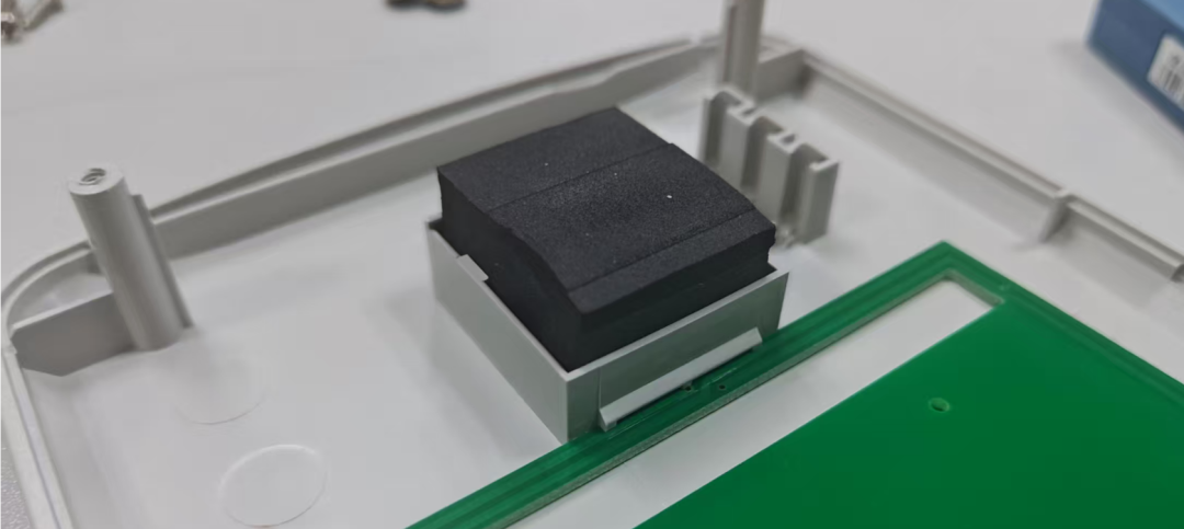
This black part is also a sponge body, just for assembly cushioning.
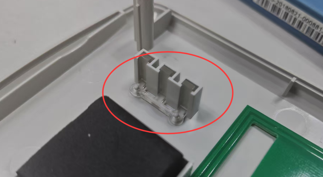
LED light guide column
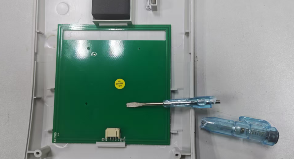
This circuit board seems to be directly clipped onto the structural component, but unfortunately, I struggled to remove this circuit board, and the screwdriver even got damaged. However, I still didn’t dare to use force, fearing to break it. I really couldn’t see the front side.
At first, I was a bit puzzled, but later I checked the information and learned that this antenna circuit board looks like it is clipped in, but it is actually firmly fixed on top with adhesive.
This is a very critical industrial design consideration, mainly for the following reasons:
The antenna board is not simply placed there, but needs to be precisely fixed in an optimal position.
l Maintain optimal distance: The 13.56MHz RFID antenna is very sensitive to its relative position with the shell. The manufacturer has already calculated and tested precisely to place the antenna board at a position that can produce the best electromagnetic field distribution. If the antenna board is loose or displaced, even by just a few millimeters, it may lead to reduced reading distance, slow reading response, or even complete failure to read.
l Prevent vibration displacement: The card reader may be moved or subjected to vibration. Using adhesive to fix it ensures that the antenna board will absolutely not move throughout the product’s lifecycle, ensuring performance remains consistent.
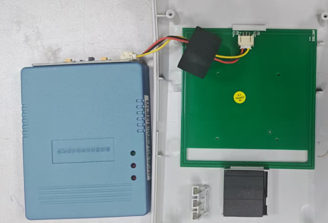
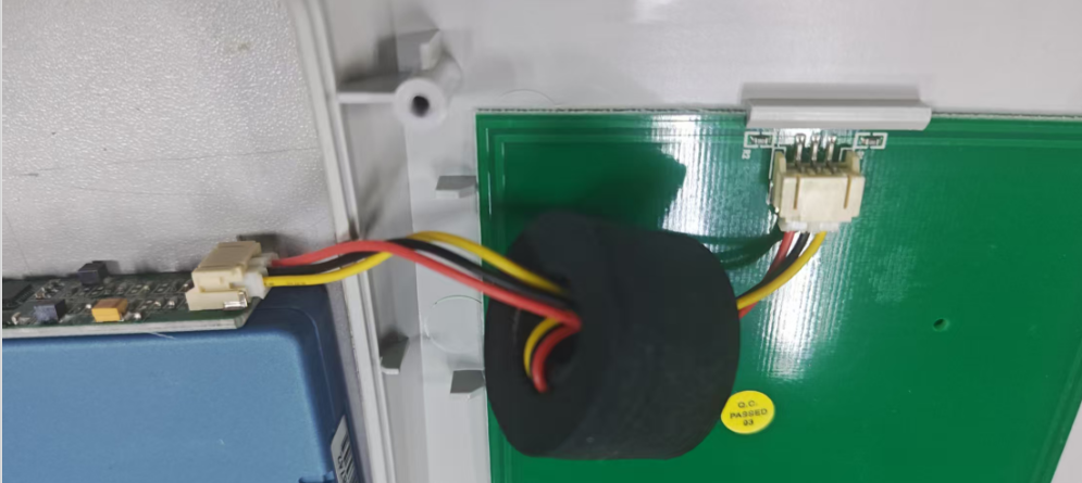
The antenna board is connected to this small box on the side.
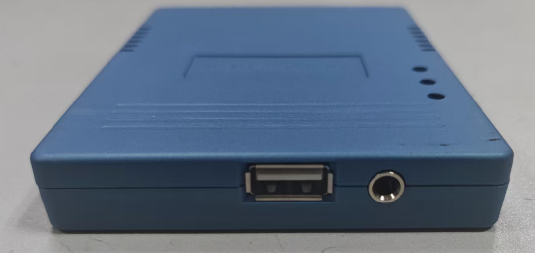
One side is the USB port for communication with the computer, and the other is a 3.5 audio jack whose purpose is unknown, as it is not exposed on the shell.
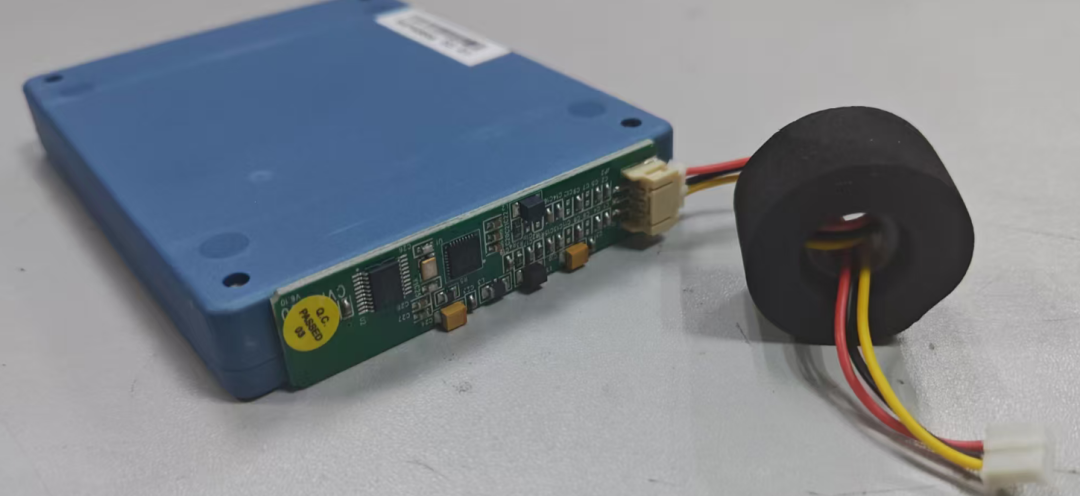
Besides the antenna board, this small box is the most critical component.
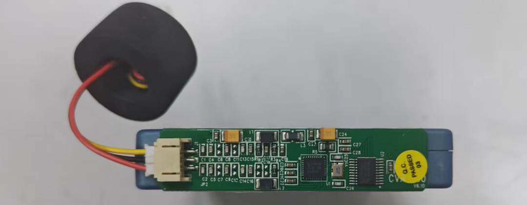
It is clearly used to process the information received from the identity card.
|
|
|
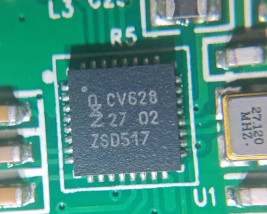
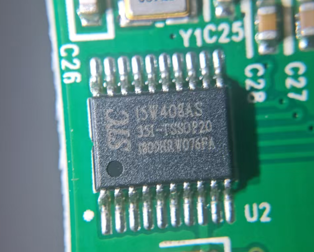
Upon investigation, the CV628 is a chip designed by Shenzhen Huashi Microelectronics Co., Ltd. specifically for the second-generation identity card reader, supporting the ISO/IEC 14443 Type B communication protocol. The CV628 internal transmitter can drive the read-write antenna and responder without additional active circuits; the receiver module can stably and efficiently demodulate and decode ISO/IEC 14443 Type B signals.
The STC 15W408AS is a microcontroller.
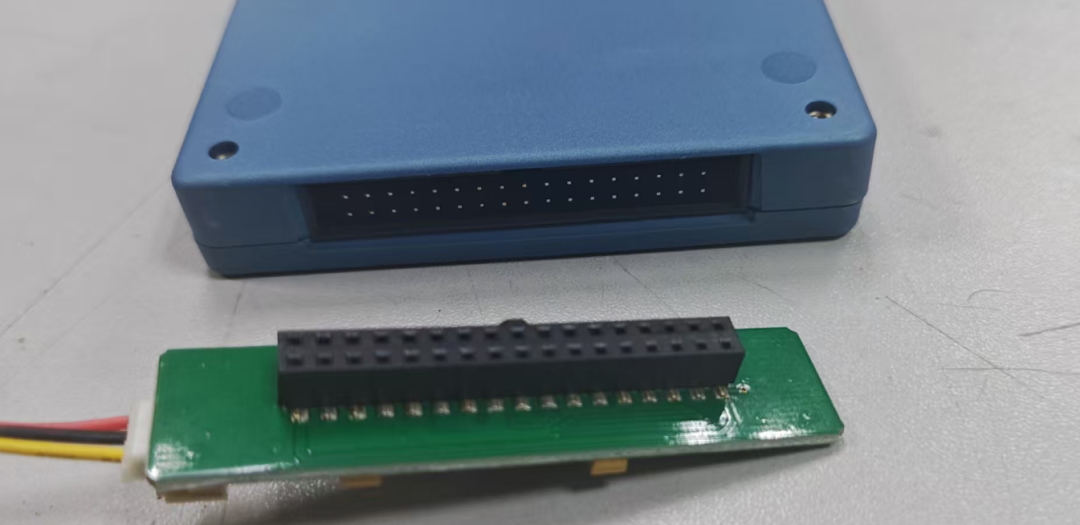
It is connected like this.
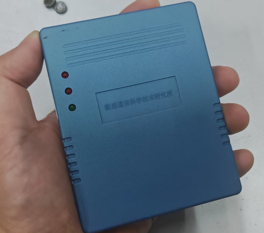
This box seems to be purchased from Huashi, with “Data Communication Science and Technology Research Institute” printed on it, giving it a very impressive and core technology feel. I checked, and it has a significant background, as it is a specialized institution under the Ministry of Public Security’s First Research Institute.
The personal information stored in the chip of our second-generation identity card (such as name, address, photo, etc.) is encrypted using specific algorithms set by the National Cryptography Administration. This is to protect citizens’ privacy and prevent information from being read indiscriminately.
Ordinary devices cannot read: Any ordinary card reader, even if it can sense the identity card, will only read a bunch of incomprehensible garbled data.
This small box labeled “Data Communication Science Research Technology Institute” stores the decryption keys authorized by the Ministry of Public Security. The reader can only establish a secure communication channel with the identity card chip through it, decrypting the encrypted data into readable plaintext information.
In summary, this small box is the most core and critical component – the security control module, with the following functions:
1. Decryption: Decrypts the encrypted data in the identity card chip into readable information.
2. Authentication: Ensures that the reader is a legally authorized device and not a counterfeit product.
3. Control: Controls which information the reader is authorized to read, preventing excessive data collection.
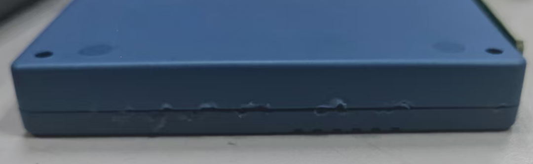
However, I didn’t expect this box to be particularly difficult to disassemble, as it seems to be glued. In the end, I was afraid of damaging this box, so I “surrendered” and will wait until I figure it out to violently disassemble it!
This disassembly taught me that the identity card operates on a 13.56MHz RFID signal, which already belongs to high-frequency signals. Besides identity cards, it is also widely used in bus cards, bank cards (contactless payment), NFC mobile phones, etc. It strikes a good balance between security, speed, and distance, making it the mainstream frequency for contactless smart cards.

In daily life, there are other frequencies used in other scenarios, such as:
¢ Low frequency (e.g., 125kHz): commonly used in access control cards, animal tags, etc. Short reading distance, slow data transmission rate.
¢ Ultra-high frequency (e.g., 860~960MHz): commonly used in logistics, warehousing, retail, etc. for long-distance inventory, with reading distances of several meters or even further, but with high power consumption and complex technology.
Related Articles:
The same product, the big manufacturers differ in DFM design and reliability design – Disassembling Seagate hard drive enclosure
Still too young! Do you really think that providing GERBER data to the board factory will guarantee 100% compliance with your data?
Scared to death! After 2800 pieces of four-layer boards were assembled, I found that the inner layer holes were shorted to ground! Is it a factory problem or a design problem?