Overall Scheme Design
The wheel-leg robot (LeTian-robot2) utilizes a linkage mechanism (see Figure 1), with the linkage controlled by servos. By controlling the servos on both sides, the overall tilt and lift of the body can be achieved. The feet are directly driven by a 4010 brushless motor without any reduction gear. Figure 2 shows the components used to build the wheel-leg robot, while Figures 3 and 4 show the PCB and the electronic components connected to the PCB.
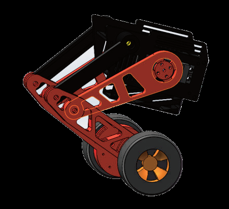
Figure 1 3D Model of the Wheel-Leg Robot
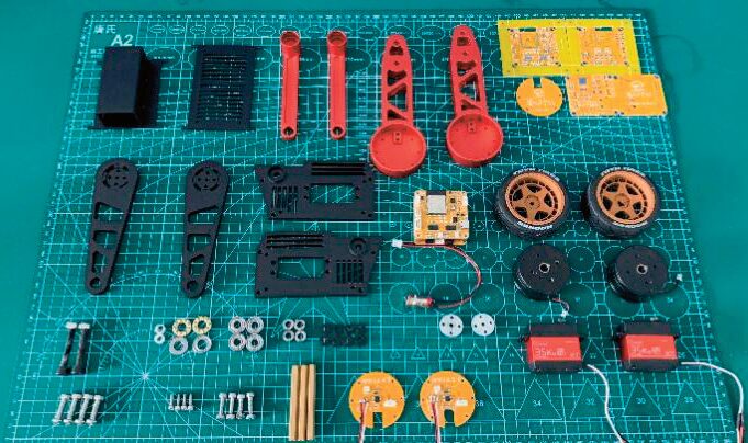
Figure 2 Component Display for Building the Wheel-Leg Robot
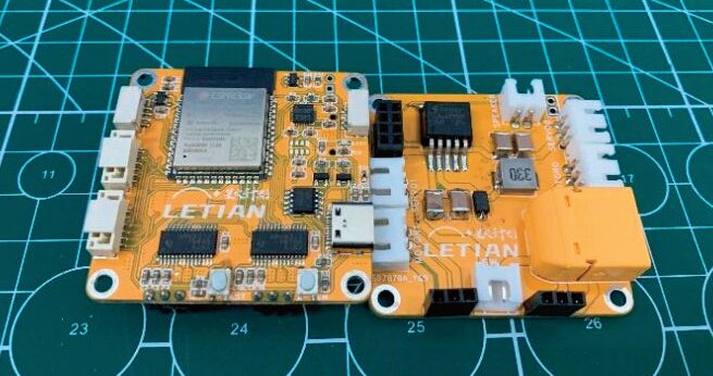
Figure 3 PCB Front

Figure 4 PCB Back
ESP32-S3 (see Figure 5) is a MCU chip that supports 2.4GHz Wi-Fi and Bluetooth 5 (LE), allowing for long-distance mode. The ESP32-S3 is equipped with a Xtensa 32-bit LX7 dual-core processor, with a maximum frequency of 240MHz, built-in 512KB SRAM (TCM), 45 programmable GPIO pins, and a rich set of communication interfaces. The ESP32-S3 supports larger capacity high-speed Octal SPI Flash and external RAM, allowing for user-configurable data and instruction caches.
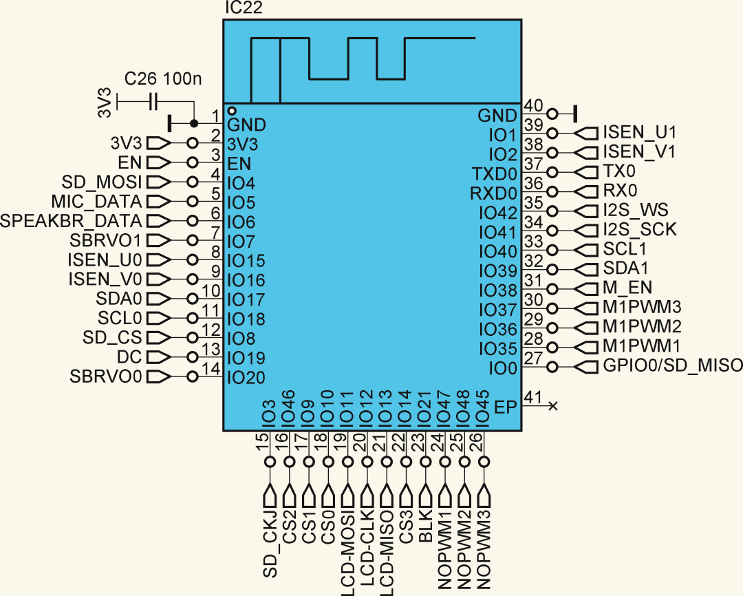
Figure 5 Main Control Chip ESP32-S3
DRV8313 provides three independently controllable half-bridge drivers. It can drive three-phase brushless DC (BLDC) motors and can also be used to drive solenoids or other loads. It is primarily used to drive a three-phase brushless DC motor in the wheel-leg robot. Each output driver channel uses N-channel power MOSFETs in a half-bridge configuration. This design connects the ground terminal of each driver to a pin to perform current sensing on each output. DRV8313 provides up to 2.5A peak current or 1.75A RMS output current on each channel of the half-bridge (with proper PCB heat dissipation at 24V and 25℃). This component offers internal shutdown features for overcurrent protection, short-circuit protection, undervoltage lockout, and over-temperature motor protection. The brushless motor driving circuit is shown in Figure 6.
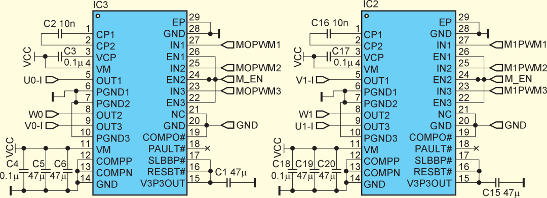
Figure 6 Brushless Motor Driving Circuit
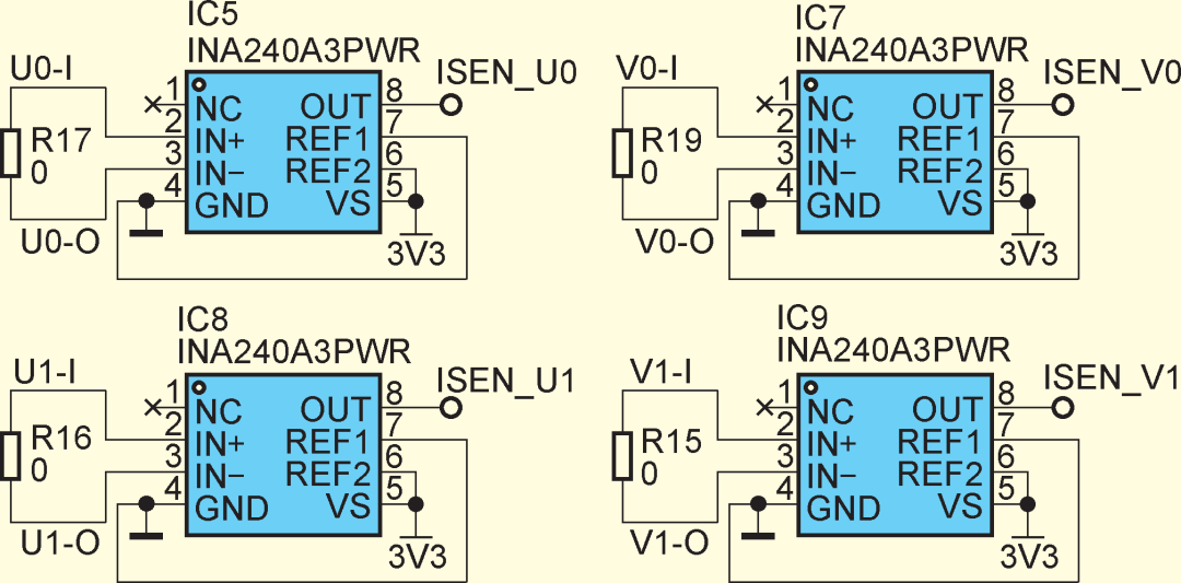
Figure 7 Current Sampling Circuit
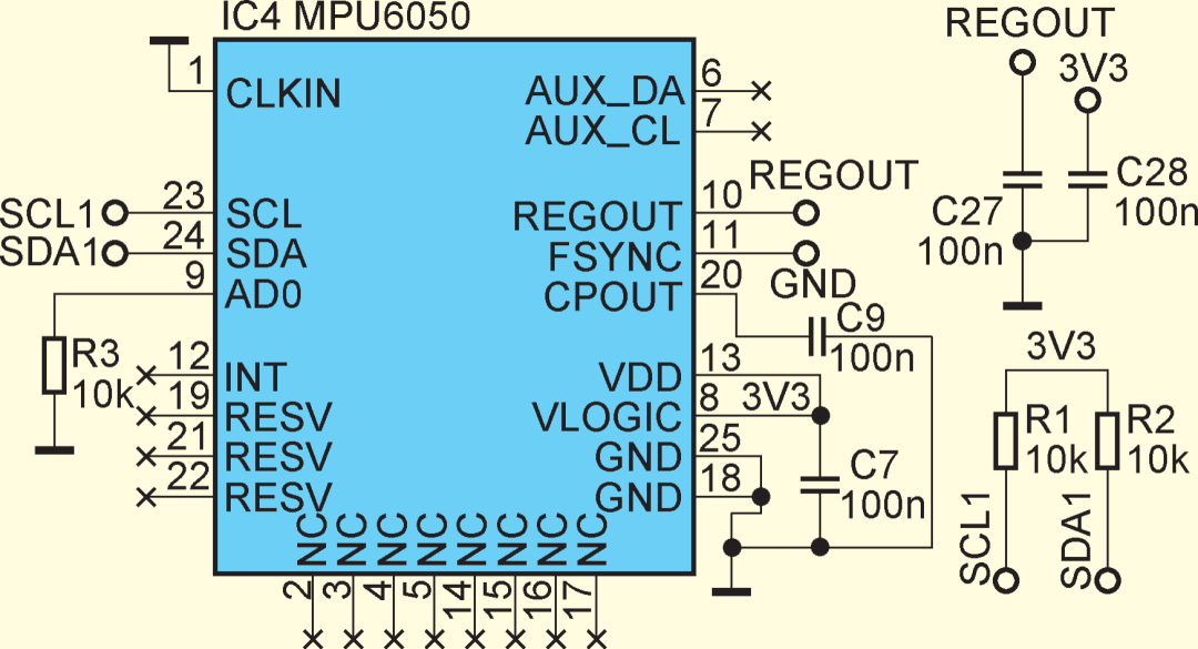
Figure 8 Motion Sensor MPU 6050

The ESP32-S3 has two modes: SPI boot mode (normal boot) and download boot mode. To achieve automatic program downloading, it must automatically enter download boot mode upon power-up, which is achieved by pulling GPIO0 and GPIO2 low simultaneously. Since GPIO2 is pulled down by default when powered on (GPIO2 may be used for reading/writing SD cards or have other functions, leading to download failures if a device is connected and the pin is high), only GPIO0 can be considered while controlling the reset pin (EN) to achieve automatic program downloading. As shown in the circuit in Figure 10, the transistor selected is the NPN type S8050, with external control signals being nDTR and nRTS, which are used on the development board as the emulator pins (JTAG emulator). However, it is not necessary to use a JTAG emulator for downloading, as the ESP32-S3 supports direct serial downloading, so these two pins can be directly used with the corresponding pins of CH340K.
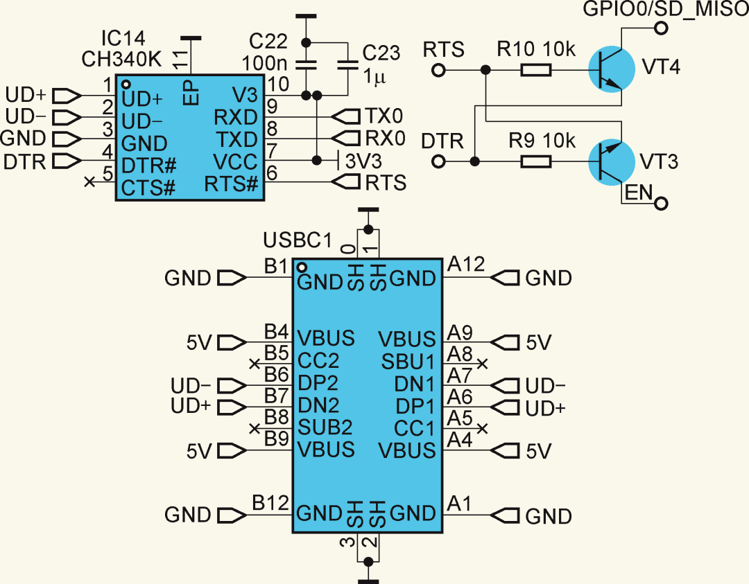
Figure 10 Automatic Programming Circuit
Figure 11 Servo Driving Circuit
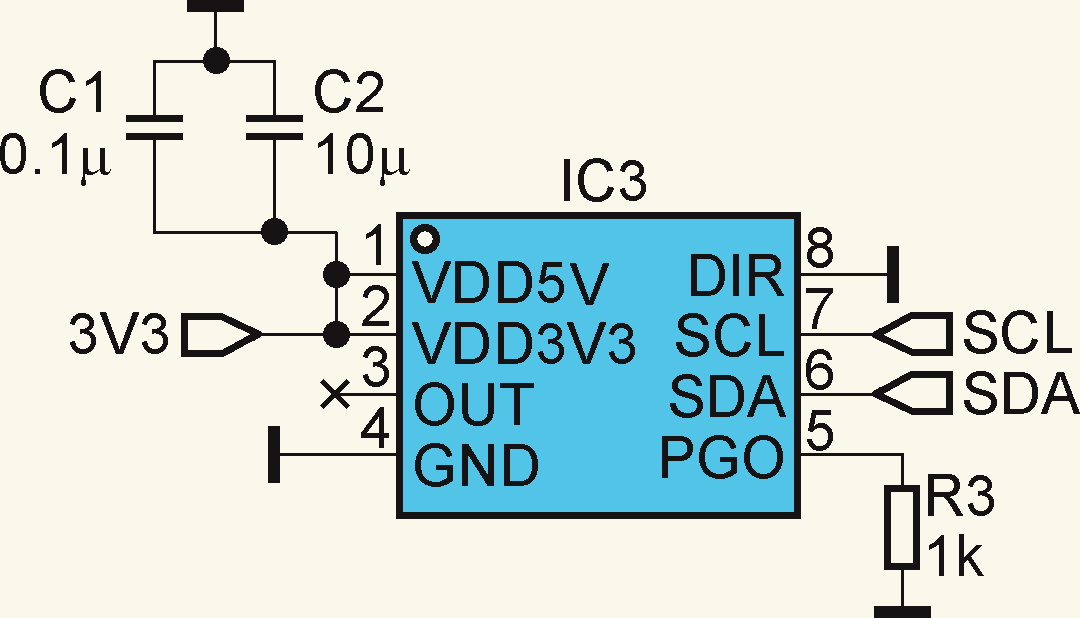
Figure 12 Magnetic Sensor AS5600 Circuit
Program Design
The overall hardware connection is shown in Figure 13, with the main control chip using ESP32-S3, reading the MPU 6050 gyroscope and accelerometer data via the I2C interface, displaying data via SPI to the display, reading microphone data and driving the amplifier via the I2S interface, and driving the servo and motor via PWM signals.
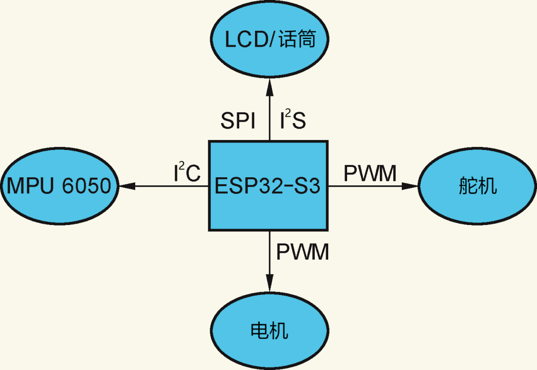
Figure 13 Overall Hardware Connection
Programming is temporarily done using the PlatformIO platform in Visual Studio Code to set up the Arduino environment for the ESP32-S3 chip, utilizing ESP32-RTOS to run programs on both cores of the ESP32-S3 simultaneously. The brushless motor drive utilizes the FOC algorithm, with the driver chip being DRV8313. The wireless function uses the low-power Bluetooth built into ESP32-S3, using the blinker library and the mobile endpoint lighting technology App for wireless connection and control.
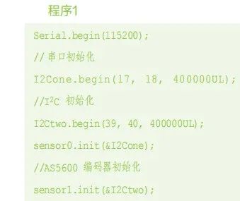
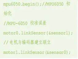
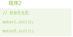
First, initialize the motor, magnetic sensor, gyroscope, servo, and Bluetooth (see Program 1), and set the PID parameters for the motor FOC algorithm accordingly (see Program 2), including parameter settings for the gyroscope and accelerometer, initialization of the servo standard signal, and design of the balancing algorithm and creation of the motor FOC algorithm.
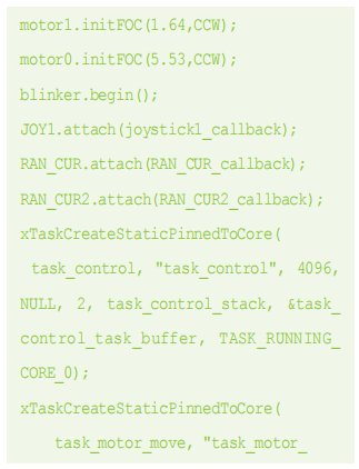
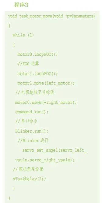
Program 3 shows the reference program for motor FOC algorithm computation, wireless communication with the lighting technology App, and servo control tasks.
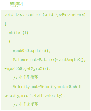
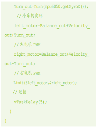
The balancing algorithm uses the classic cascade PID algorithm, assuming the motor control model is linearized, dividing the traditional cascade PID into balance loop, speed loop, and steering loop, and directly performing linear superposition to control the motor (see Program 4).
The entry parameters for the balance loop control are the body angle and angular velocity, with the return value being the upright loop motor torque control value (see Program 5).

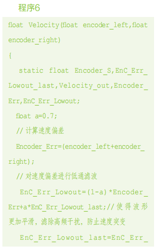
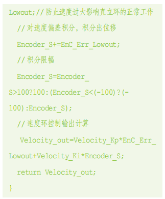
The entry parameters for the speed loop control are the actual speed values of the left and right motors, with the return value being the speed loop motor torque control value (see Program 6).
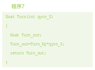
The entry parameters for the steering loop control are the angular velocity of rotation around the Z-axis, with the return value being the steering loop motor torque control value (see Program 7).
Conclusion
Currently, this project has completed the balance function of the vehicle and the wireless control function. Bluetooth connection allows control of the vehicle’s movement, as well as adjustments to the body height and tilt, though it currently does not support adaptive adjustment of the left and right servos to maintain a constant body height. Future development will shift to the ESP32-IDF environment, while continuing to optimize the control algorithm. The PCB has reserved interfaces for speakers and microphones with I2S, and since the ESP32-S3 supports offline voice recognition, offline voice control functions will be added later. The LCD interface supports a 1.28-inch circular LCD, connected with an 8Pin FPC ribbon cable, and has reserved a TF (Micro SD) card interface to support LVGL animation interaction in the future.
There are still many shortcomings in this design and production, such as further optimization of the linkage mechanism of the vehicle body, which will be improved through MATLAB simulation to better serve the control algorithm.
Text and images are sourced from Radio Magazine
Initial Review: Tang Cuimei
Second Review: Huo Xiaoyin
Final Review: Wang Xianfang