 MAKER: mattwach/Translated by: 趣无尽
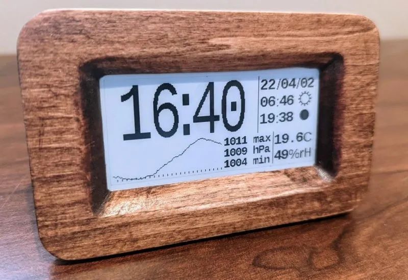
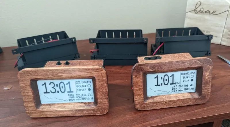
The combination of an e-paper display with any frame creates a classic look. Its unique nostalgic quality ensures that the display works created with it remain timeless.
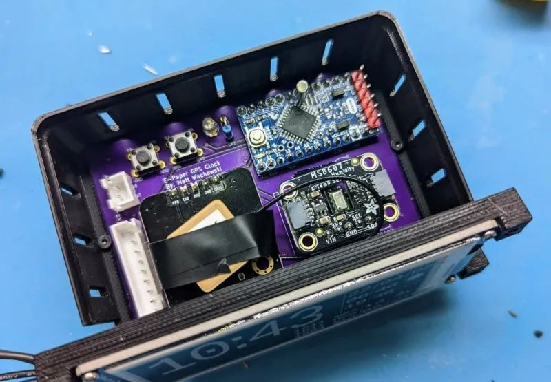
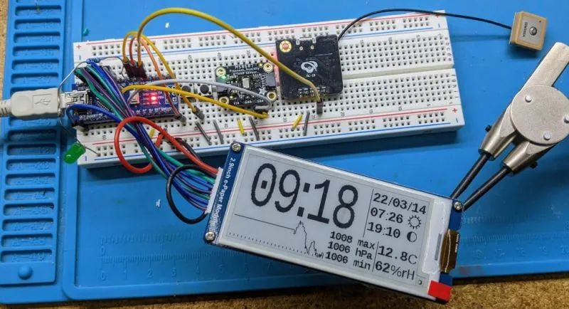
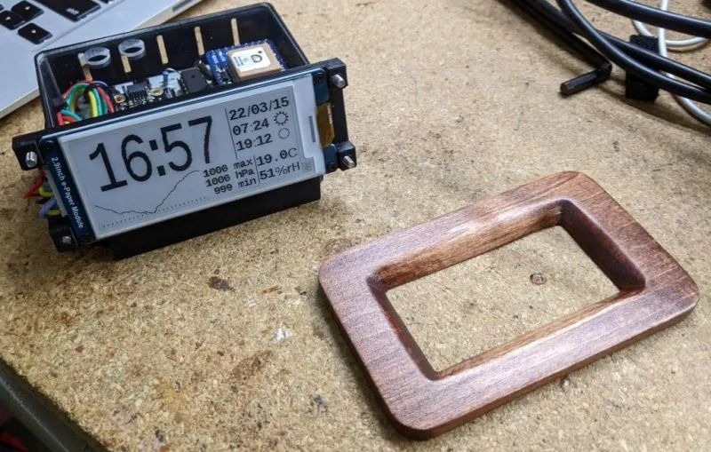
Previously, we introduced an e-paper photo frame: it can display one classic film for an entire year using a black-and-white frame display. Today, we present a retro e-paper clock that not only shows the time but also has a built-in weather forecast feature (automatically set via GPS). The display can run for about six months on just four AAA batteries, and for safety and reliability, it does not require any network connection.
Features 1. Automatically sets via GPS. 2. Displays current temperature and humidity. 3. Shows pressure chart for the past 25 hours. 4. Sunrise and sunset times. 5. Displays current moon phase. 6. Selectable between 12-hour or 24-hour modes. 7. Selectable between English and metric units.

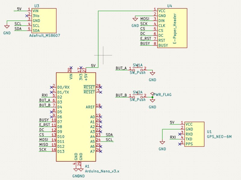
This project has three different versions: “Simple” version, “Low Power” version, and “Arduino Mini” version. The “Simple” version is built on Arduino Nano. This version reduces costs, component count, and complexity; the downside is that it requires a USB 5V adapter to power the clock. The “Low Power” version uses a 32k oscillator to maintain accurate timing with minimal power, allowing the clock to run on batteries. Both versions can be built and experimented with on a breadboard, and the final PCB can be obtained via prototyping, CNC milling, or chemical etching, with resources available for download in the project repository.

Materials List
“Simple” Version Component List

Arduino Nano × 1 Waveshare 2.9 E-Paper Module × 1 Adafruit MS8607 Pressure/Humidity/Temperature Sensor × 1 GPS Module with 9600 Baud TX × 1 Circuit Board × 1 Button Switch (for changing UTC time offset and display preferences) × Several materials for making the case × Several USB chargers × 1 Charging Cable × 1
“Low Power” Version Component List
In addition to the same components as the simple version, it adds some components: Waveshare 2.9 E-Paper Module × 1, Adafruit MS8607 Pressure/Humidity/Temperature Sensor × 1, Circuit Board × 1, Button Switch × Several materials for making the case × Several Atmega328P DIP versions × 1 32.768 Hz Crystal × 1, Adafruit GPS Module × 1, LED × 1, Resistor × 1, 10uF Capacitor × Several 100nF Capacitors × Several AAA Batteries × 43×2 Pin Header × 1 (for programming the chip via ICSP, optional) 1×2 Pin Header × 1 (for UART debugging, optional)
“Arduino Mini” Version
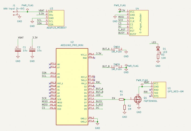
This is the simplest version. When you are in a “parts shortage”, like when the Atmega328P chip is missing, you can use this “minimal” version firmware to run. Alternatively, if you are confident in your soldering skills, you can solder a 32k crystal onto the microcontroller and use the 32k version firmware.
As shown in the schematic, it connects using a “cheap GPS” solution. You can also use other GPS (Adafruit), but you need to replace the GPS part in the schematic.
Cheap GPS (Optional)
If you feel it is unnecessary to add features (discussed in the low power components section), you can use any GPS module that can transmit NMEA strings at 9600 baud (most GPS modules can).
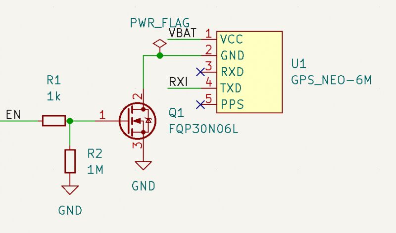
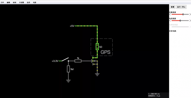
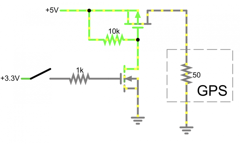
However, there is a new problem to solve: most of these units lack an enable/disable pin, and GPS units typically consume 30-100 mA of power. As shown in the figure, we can use an N-MOSFET (or similar) to create a disable switch. We can also try this in falstad .
The power switch circuit is optional. Details can be found in Appendix B.
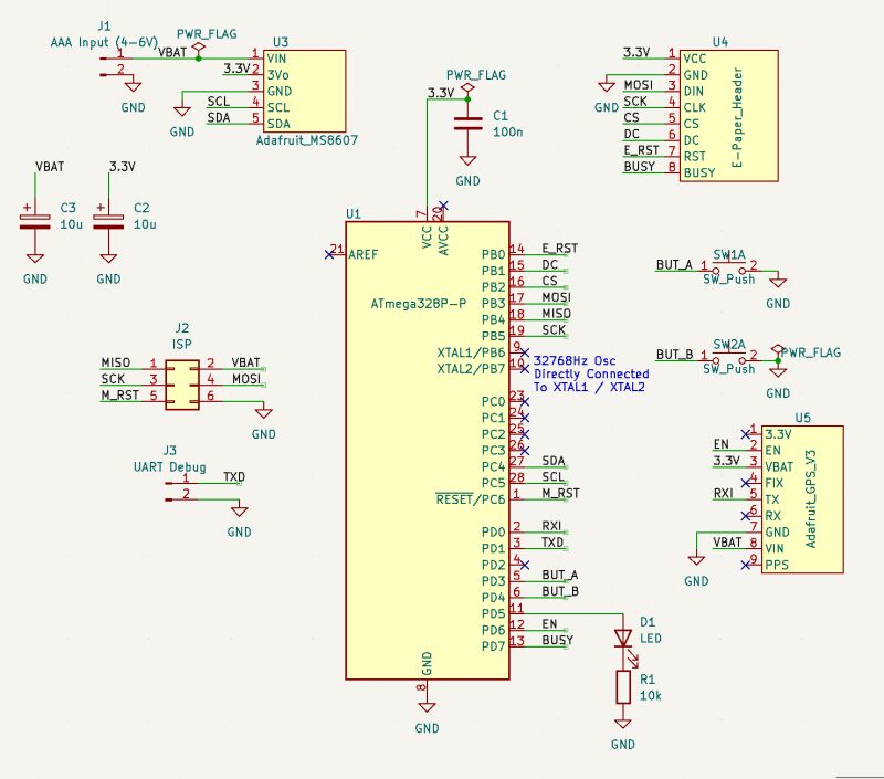
Hardware Modifications for the “Low Power” Version
If you are making the “Simple” version, you do not need to read this part. In the “Low Power” version, these modifications will greatly improve battery life.
To illustrate the issue, we will assume the power comes from a set of AAA batteries that can provide 1000 mAh. Let’s assume you are using the 32K Adafruit version and have made no modifications. Here’s an example of power breakdown.
“Sleep/Off” CPU, GPS, MS8607, and E-Paper: Measurement is 30-70uA (we assume 50uA).
Screen update: 5 mA, twice a minute: 5×2/60=166uA GPS update: once a day, 50 mA for 10 seconds. 50×10/86400=6uA MS8607 LED: 100uA Adafruit GPS pull-up resistor: 500uA. Thus, we have an average current consumption of (50+166+6+100+500)=822uA, which is equivalent to about 50 days of power.
If we remove the MS8607 LED and the GPS pull-up resistor, our power consumption will drop to 222uA, which means about 187 days of power, significantly increasing usage time.
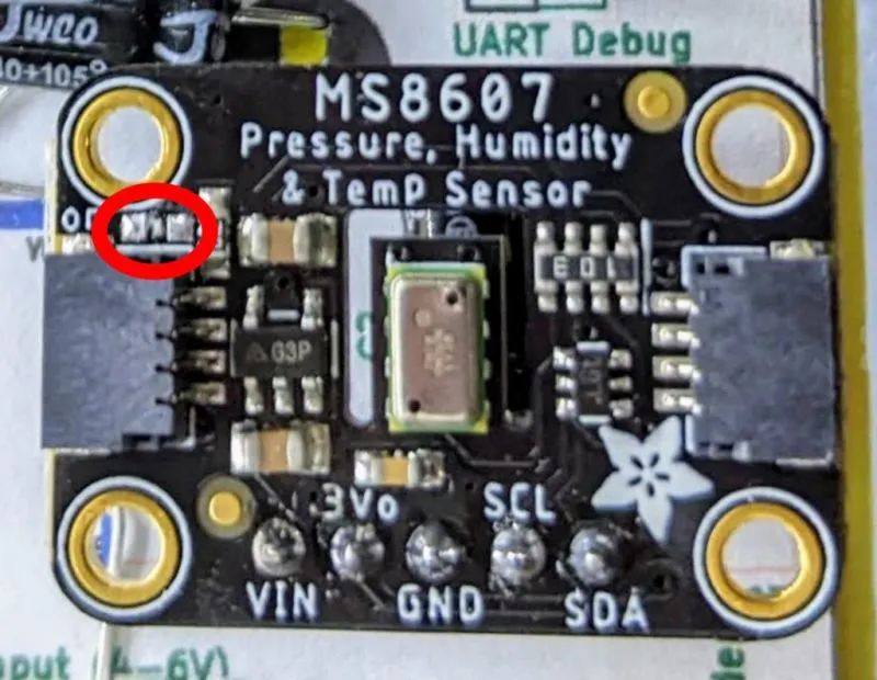
1. It is recommended to remove the LED from the MS8607.
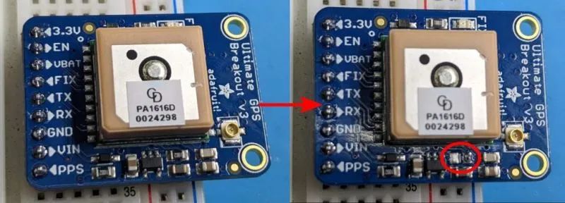
2. The pull-up resistor on the Adafruit GPS was added by Adafruit’s designers, making the EN pin optional. However, it also has a downside: when you pull it to ground (disabling GPS), about 500uA of current is consumed by the pull-up resistor.
Since the enable pin of this design is actively driven, you can remove this resistor.
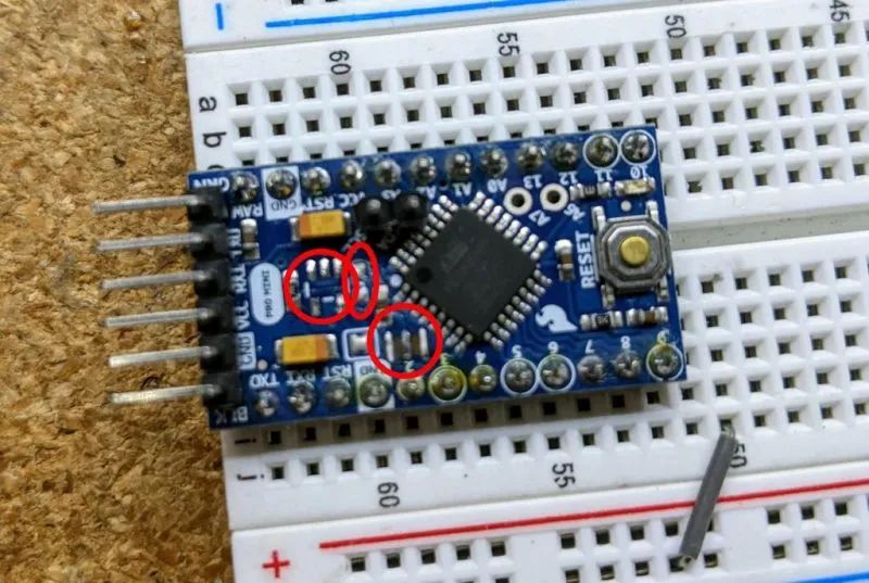
3. Professional mini modifications. Google “Arduino mini low power” for details; basically, you will want to remove the voltage regulator and LED to reduce power consumption. We switched to the voltage regulator of the MS8607 (which loses 35-55uA of power when idle at 3.3V) to power the pro mini.
4. In the pro mini diagram, I also removed the crystal oscillator to prepare for the 32K crystal chip. This can only be removed in the case of the 32K crystal version and only after reprogramming the fuses of the pro mini, which will be explained later.
Firmware In this step, I have attached the .hex files for both the nano and 32k crystal versions (both versions are compatible with pro-mini; if you are unsure which version to use, just use the nano version).
If you want to build/modify the source code yourself, you can visit GitHub: https://github.com/mattwach/epaper_clock
Build Your Own .hex Firmware File (Optional) Please note that this code does not use the Arduino library because the generated code is too large to install on the Atmega328P (personal preference).
It is written in C language, using the Arduino and AVR base libraries as a foundation. If you want to compile the code, you need to install the (free) avr-gcc tool and copy the epaper project source code. Then go to the firmware/ directory and enter.
makeIf the code builds successfully, you can open the Makefile to check these options.
# This is the Low-power stand alone chip configuration.CLOCK_MODE ?= USE_32K_CRYSTALUART_MODE ?= HARDWARE_UARTF_CPU ?= 8000000
# This is the easy-to-build firmware that is based on an Arduino Nano#CLOCK_MODE ?= USE_CPU_CRYSTAL#UART_MODE ?= SOFTWARE_UART#F_CPU ?= 16000000
If you are building the 32k crystal firmware, the configuration is already correct. If you are building the nano version, you need to comment out the 32k part, uncomment the nano part, and then make again.
There is also a special debug mode that dumps information via hardware UART at 9600 baud. You can ignore this for now, but keep it in mind as it may be useful later.
# Uncomment to activate debug via the UART TX (9600 baud)#DEBUG_CFLAG := -DDEBUGFinally, you can decide how long the GPS should be activated by changing a few variables. By default, it runs once a day, but if the GPS takes a long time to lock, it will reduce the running frequency to save battery. Please read all relevant information in src/gps.c.
Reference Links avr-gcc tool: https://www.pololu.com/docs/0J61/6.3 GitHub: https://github.com/mattwach/epaper_clock
Source code, firmware, Makefile, and other files can be downloaded from the project repository: https://make.quwj.com/project/434
Use ICSP to Upload Firmware
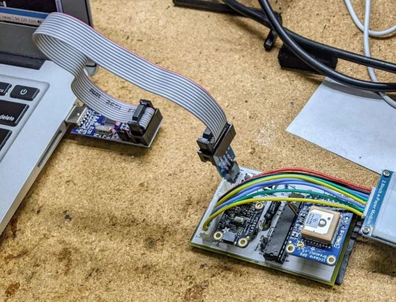
This step is for those uploading code to a standalone Atmega328P chip. If you are uploading to an Arduino Nano, please skip to the next step.
You will need an ISP (or ICSP) programmer. You can make one using a spare Arduino Uno/Nano. You can search Google for “Arduino ISP Programmer”. Please note that many of these guides assume your real goal is to install a bootloader, but for us, we do not need a bootloader as we will upload the .hex file directly using ICSP.
Brown-out Detection On my Atmega328P, the brown-out detection is set to 3.5V (possibly an older version), so I disable brown-out detection with this command.
/usr/bin/avrdude -patmega328p -cusbasp -Uefuse:w:0xFF:mYour setup may differ depending on your “ISP programmer” (-c option). You may also not need to set it, just in case.
Using Avrdude
We can use a free tool called avrdude to upload the hex files it creates to your Uno/Nano. We can also download and use avrdude directly from the command line.
Run an upload with the Arduino IDE open and the output log visible (e.g., a blinking demo or another demo), then copy the command it uses. Or read the official avrdude documentation or find online tutorials on how to use avrdude. Here is the avrdude command I used in the nano version (uploaded via make), for reference.
/usr/bin/avrdude \ -v \ -patmega328p \ -carduino \ -P/dev/ttyUSB0 \ -b57600 \ -D \ -Uflash:w:epaper_firmware_using_arduino_nano.hex:iThis is the one I used in the ISP version
/usr/bin/avrdude \ -v \ -patmega328p \ -cusbasp \ -Uflash:w:epaper_firmware_using_32k_crystal.hex:iI am using Linux. Mac and Windows also work fine, but options like -P may differ (e.g., in Windows it might be -PCOM1).
Reference Links avrdude: https://www.nongnu.org/avrdude/ Arduino IDE: https://www.arduino.cc/en/software
Firmware files can be downloaded from the project repository: https://make.quwj.com/project/434
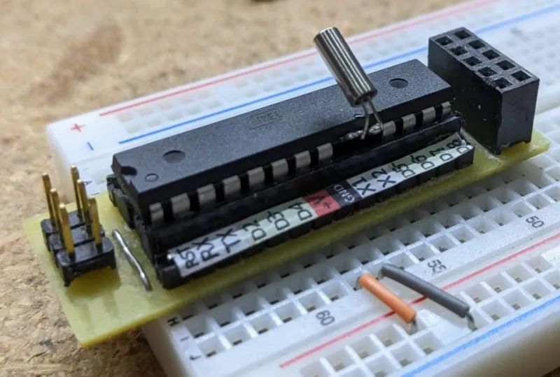
32K Crystal
Selecting the “Simple” version can skip this step. If you are using the 32k crystal firmware, you will need to install the crystal for the firmware to function.
First, you need to configure the internal fuses of the ATMega328P to use the internal 8Mhz crystal.
Doing this step first is important because the 32K crystal will replace any existing crystals. If you do not change these fuses, the chip will become unresponsive until you reconnect an 8 or 16Mhz oscillator.
The Arduino pro mini also requires ISP to change the fuses (but I may be wrong). I searched for “Arduino ISP” to get the correct pin mapping to connect the ISP connector to the breadboard.
After connecting my ISP programmer, I can check the current fuse configuration with this command.
$ avrdude -patmega328p -cusbasp...avrdude: safemode: Fuses OK (E:FF, H:DE, L:E2)L:E2 is the setting we want for the internal 8mhz. If your value differs, you can use a command similar to this to update it.
/usr/bin/avrdude -patmega328p -cusbasp -Ulfuse:w:0xE2:mThen check again.
Once the fuses are set, you can solder the crystal. It is recommended to connect the crystal directly to the microcontroller pins to minimize stray capacitance. Too much capacitance can cause the crystal to take longer to start oscillating (or fail to start).
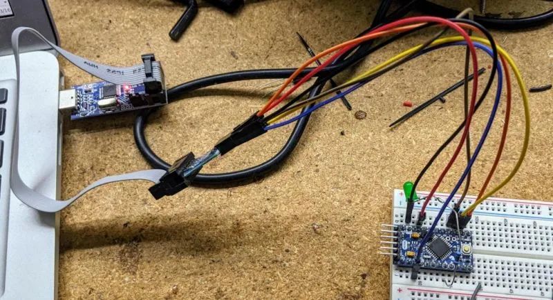
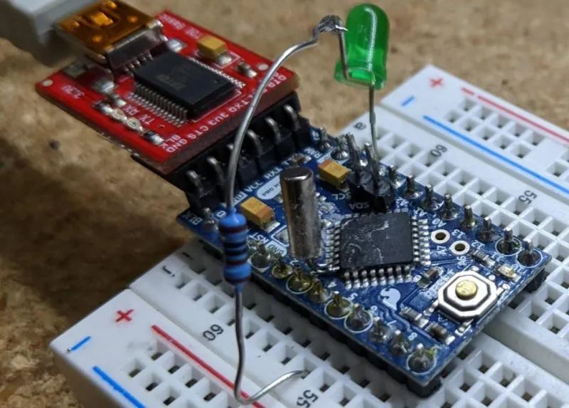
Step One (Optional)
Please refer to steps 1, 2, or 3 to choose the schematic design.
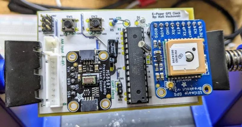
1. You can verify the current situation on a breadboard by simply grounding an LED/Resistor from D5 and then uploading the firmware. If everything is working correctly, the LED will blink once a second. 2. Add the E-Paper display. The data on the display may not be correct, but it should show some data. 3. Add the PHT module and verify that it works. 4. Add the GPS module. If the tests are successful, we can transfer everything to a more “permanent” fixture.
Assembling the Circuit Board
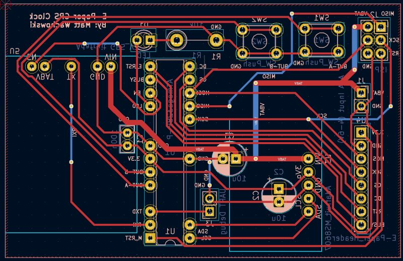
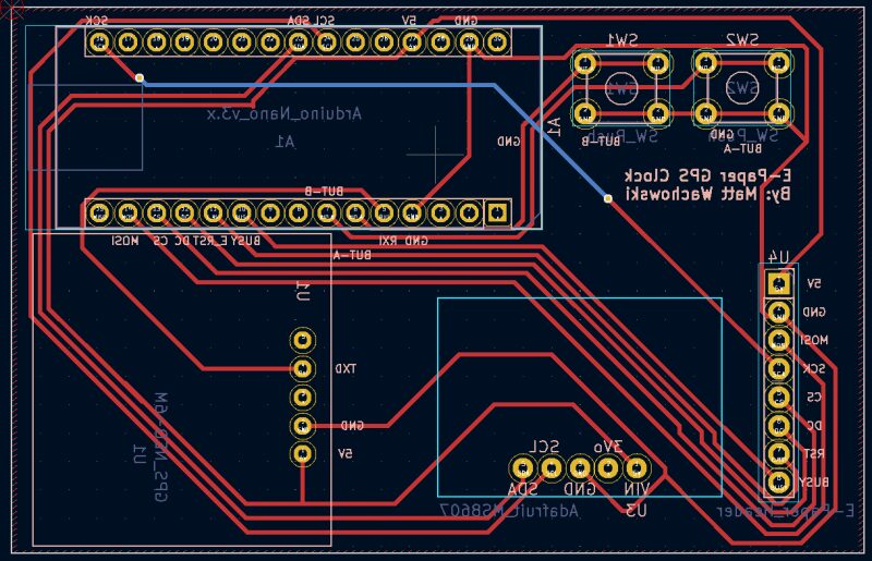
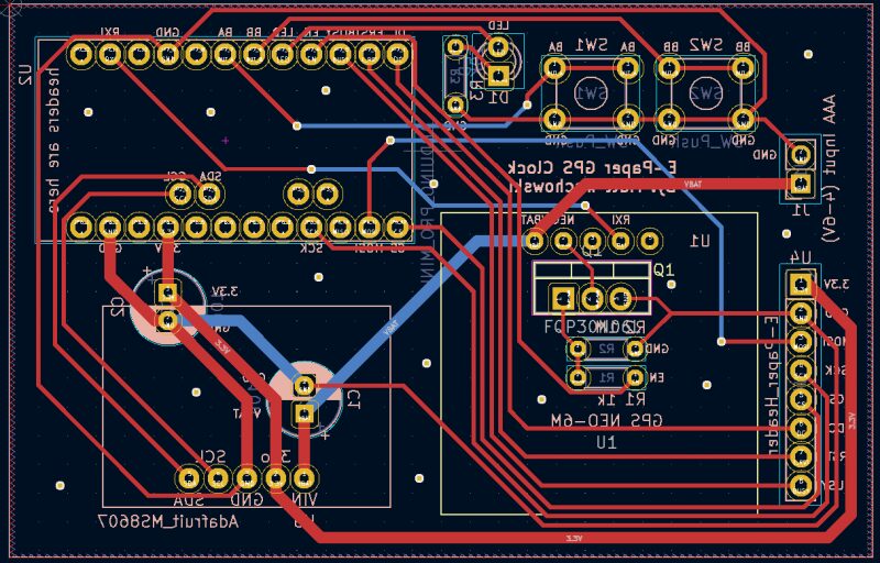
You can choose to use perf boards, CNC cut boards, or send them to a factory for customization.
The Kicad design files can be found in the schematic/ directory. There are three hardware options available (all shown from the back as this is how you hand-wire them).
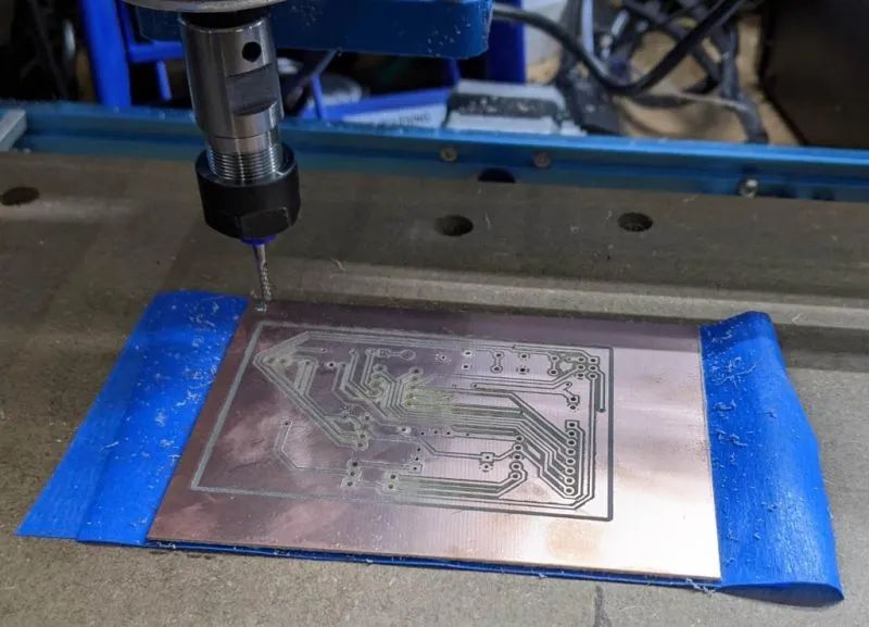
I used CNC to make the ATMega328P version. If you have never CNC cut a PCB but are very interested, you can try searching “3018 PCB” on Google, and you will find many videos and articles on this topic.
Gap settings are 0.4 mm, but you can go narrower (but not wider). I used Flatcam to convert Kicad’s Gerber output to G code.
Reference Links Kicad: https://www.kicad.org/ Flatcam: http://flatcam.org/ schematic/: https://github.com/mattwach/epaper_clock/tree/main/schematic
Designing the Enclosure
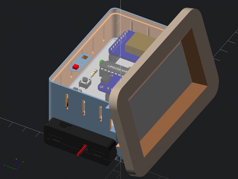
The enclosure design uses a 3D printed support structure and two CNC parts: a top cover and a front panel. The CNC parts are made of wood, which looks better than plastic. The entire enclosure can be pre-designed in OpenSCAD.
Using a layer height of 0.2 mm, it takes about five hours to print the main structure.
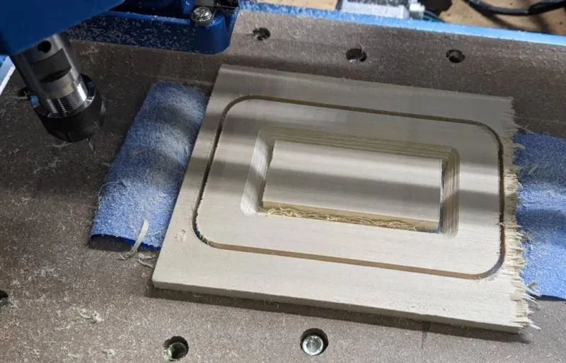
Using OpenSCAD’s “projection” function, I created 2D DXF files for the top cover and front panel.
I usually use a free program called “Carbide Create” to create G code for CNC machines. However, the panel has a 45-degree chamfer, and Carbide Create is too basic a program to handle this well. So I tried a different program called “CamBam”, which worked very well. (CamBam is not free, but it can be used for free 40 times.)
Reference Links case_design: https://github.com/mattwach/epaper_clock/tree/main/case_design OpenSCAD: https://openscad.org/ projection: https://en.wikibooks.org/wiki/OpenSCAD_User_Manual/Using_the_2D_Subsystem#3D_to_2D_Projection Carbide Create: https://carbide3d.com/carbidecreate/ CamBam: http://www.cambam.info/
Appendix A: Clock Drift Correction (Optional)
32k/CPU crystals will not be perfect. When GPS is on, it will correct drift. However, if the drift is poor or your GPS signal is weak, you can also apply a correction in the firmware. You will need to build code; at the top of main.c, there are some commented-out definitions.
// Clock drift correction// If your clock runs too fast or too slow, then you can enable these//#define CORRECT_CLOCK_DRIFT// number of seconds that a second should be added or removed//#define CLOCK_DRIFT_SECONDS_PER_CORRECT 1800// define this if the clock is too slow, otherwise leave it commented out//#define CLOCK_DRIFT_TOO_SLOWYou can uncomment the above two #define statements to enable correction.
If your clock is already slow, simply uncomment CLOCK_DRIFT_TOO_SLOW; if your clock is too fast, do not uncomment it. The only thing to do is to set CLOCK_DRIFT_SECONDS_PER_CORRECT…
Mathematical Method After about a day, check how much the clock has drifted. For example, you waited for 23 hours. If you see the clock is slow by 10s, the correction formula is: (3600×23)/10 = 8280 seconds per correction.
#define CORRECT_CLOCK_DRIFT#define CLOCK_DRIFT_SECONDS_PER_CORRECT 8280#define CLOCK_DRIFT_TOO_SLOWOther Methods Start with a value of 5000 and observe whether the clock is still too fast or too slow, then adjust it. Still too slow? Try 2500. Too fast? Try 10000. Keep records and adjust repeatedly until you reach an acceptable value.
Appendix B: Cheap GPS Power Control (About BS170 N-MOSFET)

Returning to the previous step about “cheap GPS”, which described the power control circuit, the above power cut-off circuit is called a “low side switch”. Its advantage is that it is relatively easy to understand and has fewer components, but there are still some design issues.
The ground of the GPS is not connected to GND, but is connected to the MOSFET. This means that the UART signal from the GPS to the microcontroller will have the MOSFET’s voltage drop (Vds) added to it, increasing noise sensitivity and potentially causing errors.
If your microcontroller’s input is specified as 3.3V maximum, you would not want to use this design (choosing ATMega328P has no such limitation).
3.3V (the EN pin above) is not a strong enough turn-on voltage for each MOSFET. UART is a digital signal, and the ground difference is not large, so it may work anyway?
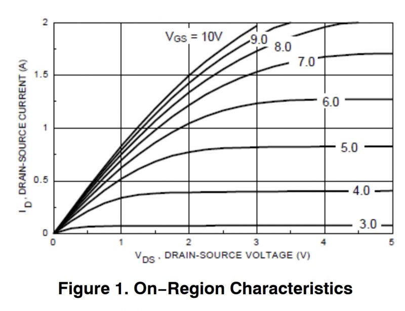
I tried it, and it worked well at first, but over time, I gradually found that it was unreliable. To understand the reason, we refer to the characteristic curve of the BS170 that I initially chose as my N-MOSFET.
At 3.3V on the X-axis, we will sit between the 3.0 and 4.0V lines on the graph. So, maybe we will get 100mA? Maybe enough?
The multimeter tells me that the GPS consumes 40-60mA, but I think this is an average value. Depending on what the GPS is trying to do, it just needs more current than the transistor can allow, so the ground voltage of the GPS (MOSFET drain) rises. This causes both UART errors and lowers the overall voltage of the GPS device, which sometimes still works and sometimes enters a reset loop.
One solution is to use a “high side” power circuit, which requires adding a P-MOSFET to achieve this goal. It eliminates the separate grounding issue and provides a full 5V (battery) gate voltage fluctuation, which will turn the relevant P-MOSFET fully on.
An example of a high-side design in falstad.
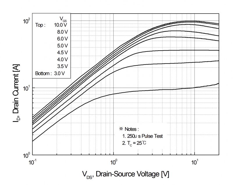
Currently, I have purchased a PCB with low-end wiring, so my secondary solution is to abandon the BS170 and replace it with an FQP30N06L. This higher current MOSFET (maximum 30A!) seems to be an overkill, but its curve looks much better. At 3.3V, there is about 10A of current headroom, improved by 100 times compared to the BS170, and it should be sufficient and stable now.
The characteristic curve of the N-MOSFET: https://www.onsemi.com/pdf/datasheet/mmbf170-d.pdf
The code used in the project can be downloaded from the project repository: https://make.quwj.com/project/434
via instructables.com/E-Paper-Clock/
Links in the text can be clicked to read the original at the end of the article

More Exciting Content