Click Mushroom Cloud Creation to follow us
The following video is sourced from Dakaizhi Chuang
↑Demo Video↑
【Creation Background】
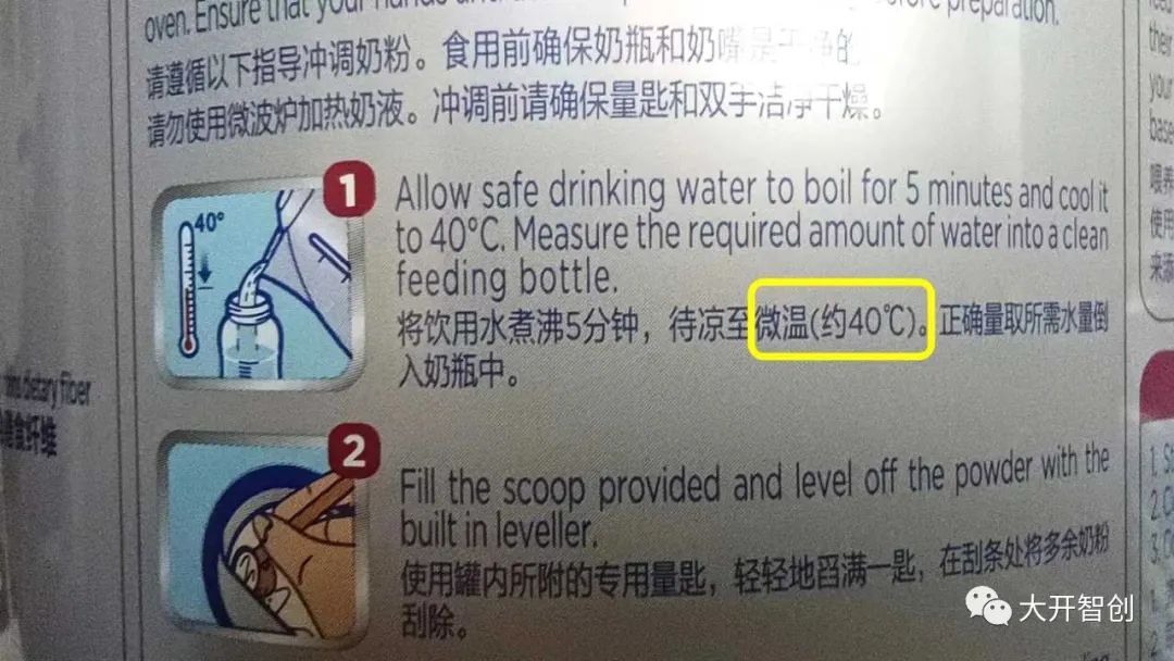
Figure 1
When preparing milk powder, the appropriate water temperature is key to maximizing the retention of nutrients. Typically, the milk powder can will have a brewing guide, which includes recommendations for water temperature (as shown in Figure 1). Most infant milk powder brands recommend a water temperature range of 40℃~50℃. So how can we obtain warm water at the appropriate temperature? People generally use warm milk (water) heaters, natural cooling, or mixing hot and cold water.
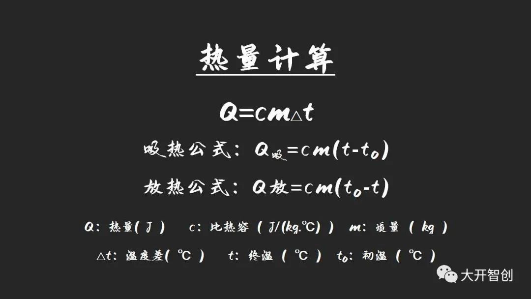
Figure 2
Sometimes, to save time, I use hot boiling water mixed with cold water, but I feel that the temperature achieved is inconsistent. This raises the question: how can we more accurately mix to achieve the right warm water temperature (how much hot and cold water to mix)? After some contemplation, I realized this is actually a common physics problem, and there are existing heat formulas (see Figure 2) that can be used. By leveraging maker equipment and technology, we can achieve smart temperature measurement and automatic calculation to solve this.
Of course, some friends may think that mixing hot and cold water is not advisable. Let’s set aside the issue of preparing milk powder and focus on how to mix warm water instead.
At the beginning of the project, I used an Arduino Uno as the main control board, along with an LCD12864 display. However, due to the large amount of information to be displayed, the display effect was not ideal. At this time, I received a new Airborne Board from DFRobot, which outperformed the Arduino Uno in all aspects. The 2.8-inch color screen it is equipped with delighted me. Thus, I adjusted the original hardware configuration plan to use the Airborne Board as the main control board and redesigned the original information display method.
【Understanding the Airborne Board】
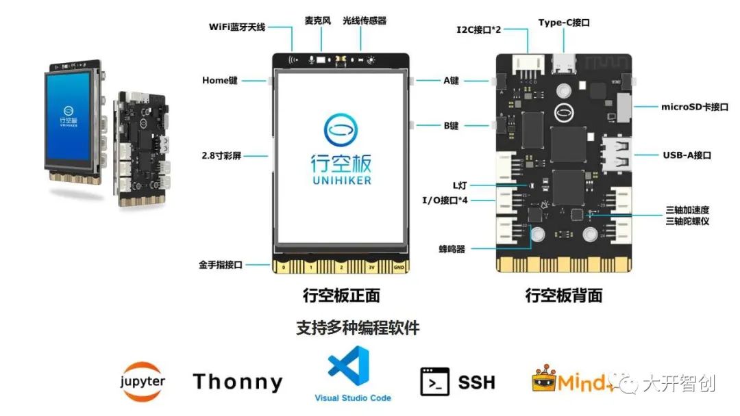
Figure 3
The Airborne Board (see Figure 3) is a new generation of domestic open-source hardware designed for learning and using Python. It adopts a single-board computer architecture, integrating an LCD color screen, WiFi, Bluetooth, various commonly used sensors, and rich expansion interfaces. From the perspective of hardware configuration and parameters, it is a very powerful main control board that can support the creation of more powerful maker projects. What’s even better is that it supports various programming software and connection methods, making it easier for users to learn Python. It also provides an entry-level graphical programming environment, allowing even elementary school students to get started quickly.
For friends who are used to using Mind+ software, please note that the Mind+ version suitable for the Airborne Board has not yet been officially released. You can download the beta version from https://wiki.unihiker.com/.
【Function Description】
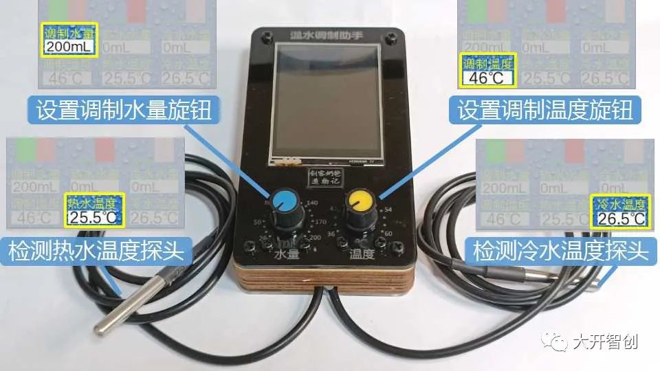
Figure 4
This project is equipped with two DS18B20 waterproof temperature sensors, capable of detecting the temperature of two water paths simultaneously. The panel has two knobs used to set the volume (amount) and temperature of the warm water to be mixed (see Figure 4).
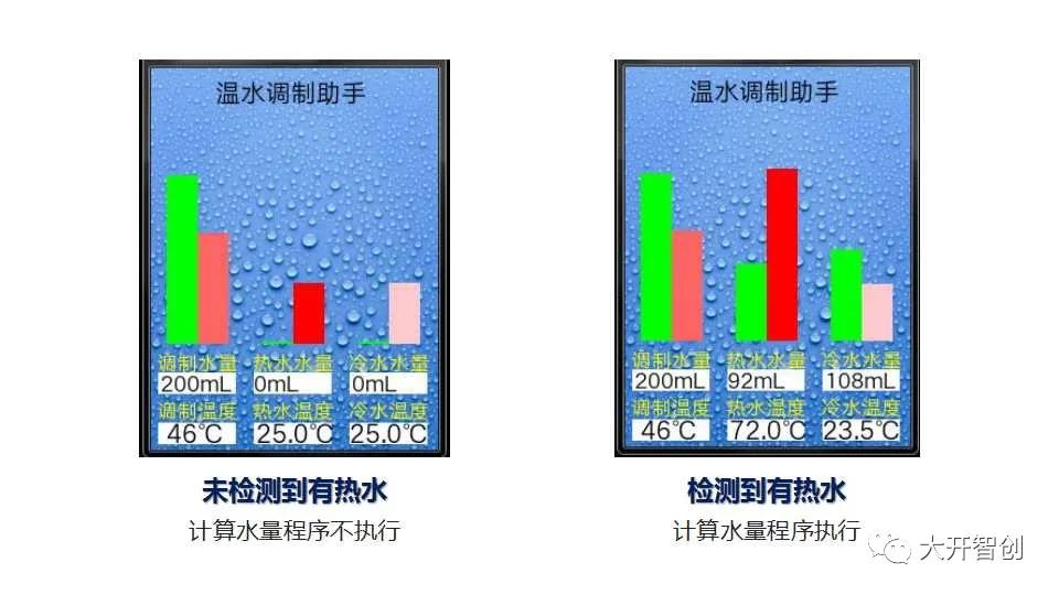 Figure 5
When the temperature of the hot water is higher than the desired mixing temperature, the program to calculate water volume will be activated, determining the required amounts of hot and cold water to mix (see Figure 5). The three volume values and three temperature values mentioned above will be displayed in real time on the screen, accompanied by a bar graph for intuitive presentation.
Production Process
1.Material Preparation
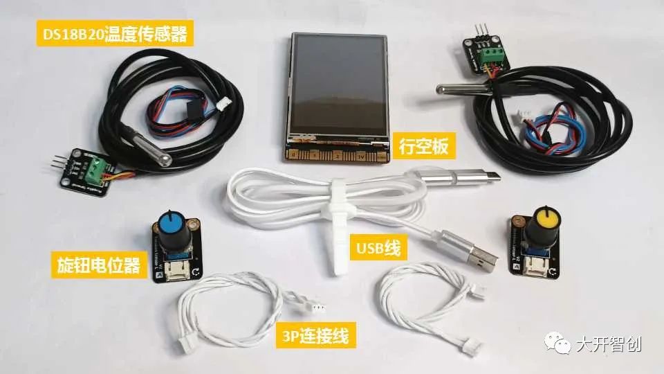
Figure 6
This project uses the following hardware materials (Figure 6):
1. Airborne Board 1 piece
2. DS18B20 temperature sensor (waterproof) 2 pieces
3. Knob potentiometer 2 pieces
4. USB cable 1 piece
5. 3P connecting wires 4 pieces
2.Hardware Setup
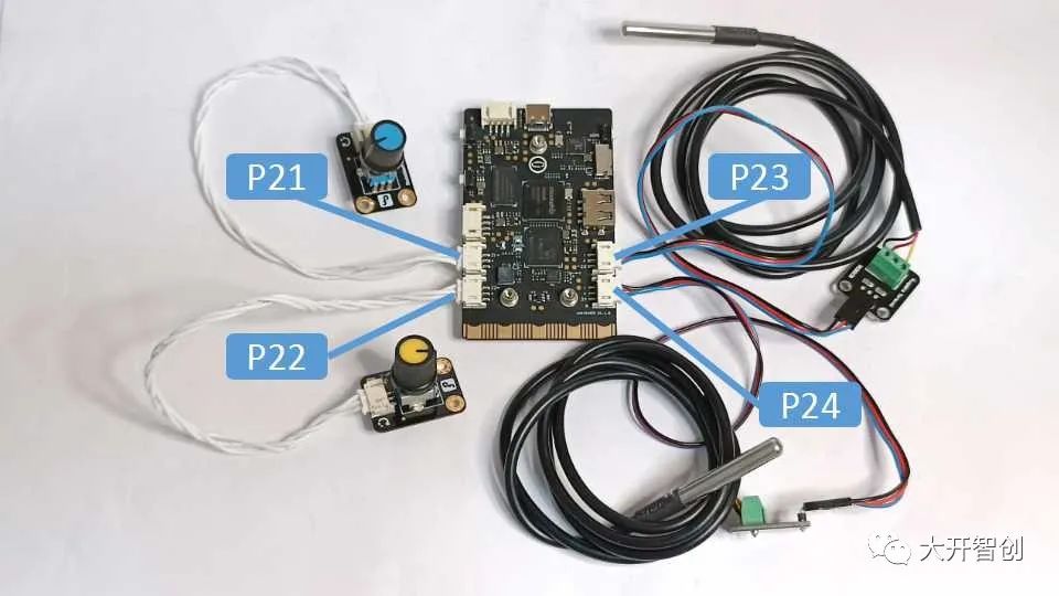
Figure 7
The Airborne Board integrates four 3Pin I/O interfaces, with pins P21, P22, P23, and P24. The corresponding pins for the four sensors used in this project are as follows (see physical diagram in Figure 7):
Knob potentiometer (blue)——P21
Knob potentiometer (yellow)——P22
DS18B20 temperature sensor ——P23
DS18B20 temperature sensor ——P24
3.Program Design
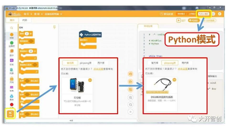
Figure 8
The program for this project is written using Mind+ software, version V1.7.2 RC3.0. When writing programs for the Airborne Board, you need to switch to “Python mode” and find and load the “Airborne Board” library in “Extensions”. This project uses the DS18B20 temperature sensor, so the “DS18B20 Temperature Sensor” library also needs to be loaded.
When programming the Airborne Board using Mind+, you can use graphical block modules for programming or use code programming. Below is a code example for this project, presented in six parts.
(1)Load Required Libraries
Temperature Mixing Assistant.py by Huai Ruogu
# Load required libraries
from pinpong.extension.unihiker import *
from pinpong.board import Board,Pin
from pinpong.board import DS18B20
from unihiker import GUI(2)Define Function “numberMap” (Mapping)
# Define function: mapping
def numberMap(x, in_min, in_max, out_min, out_max):
return (x-in_min)*(out_max-out_min)/(in_max-in_min)+out_min(3)Define Function “calculation” (Calculation)
# Custom function: calculation, used to calculate the required amounts of hot and cold water
def calculation():
    ok = 0   # Completion flag, default value is 0 (no)
    m_hot = 0  # Set initial value of hot water to 0mL(g), preparing to solve through enumeration
    while not ((ok == 1)):
        # Repeat the following instructions until an answer is found
        m_hot = (m_hot + 1)   # Increment the value of hot water by 1mL each loop
        m_cold = (m_total - m_hot)  # The value of cold water equals the total water volume minus the value of hot water
        Q1 = (4.2 * (m_hot * (t_hot - t_end)))    # Calculate the heat released by hot water Q1
        Q2 = (4.2 * (m_cold * (t_end - t_cold)))  # Calculate the heat absorbed by cold water Q2
        if ((abs((Q1 - Q2))) < 200): # When the values of Q1 and Q2 are very close (completely equal is difficult)
            ok = 1                  # Indicates the solution was successful, mark as 1 (yes)
        M1.config(text=(str(m_hot) + str("mL")))   # Update the value of hot water
        SQU20.config(h=(-0.7 * m_hot))           # Update the height of the rectangle corresponding to hot water
        M2.config(text=(str(m_cold) + str("mL"))) # Update the value of cold water
SQU30.config(h=(-0.7 * m_cold)) # Update the height of the rectangle corresponding to cold water(4)Initialization Settings
Board().begin()  # Main control board initialization
u_gui=GUI()  # Instantiate GUI
p_p21_analog=Pin(Pin.P21,Pin.ANALOG)   # Set P21 as analog input pin, connected to knob potentiometer 1
p_p22_analog=Pin(Pin.P22,Pin.ANALOG)   # Set P22 as analog input pin, connected to knob potentiometer 2
ds1_hot= DS18B20(Pin((Pin.P23)))  # Set P23 as object ds1_hot, connected to DS18B20, used to detect hot water temperature
ds1_cold= DS18B20(Pin((Pin.P24))) # Set P24 as object ds1_cold, connected to DS18B20, used to detect cold water temperature(5)Set User Interface
# Set user interface
BG=u_gui.draw_image(image="bg.png",x=0,y=0) # Set background image
WORD0=u_gui.draw_text(text="Warm Water Mixing Assistant",x=54,y=5,font_size=15, color="#000000")
WORD10=u_gui.draw_text(text="Water Volume",x=5,y=235,font_size=12, color="#FFFF00")
WORD11=u_gui.draw_text(text="Mixing Temperature",x=5,y=275,font_size=12, color="#FFFF00")
BG10=u_gui.fill_rect(x=6,y=255,w=64,h=17,color="#FFFFFF")
M0=u_gui.draw_text(text="0mL",x=8,y=250,font_size=13, color="#000000")
BG11=u_gui.fill_rect(x=6,y=297,w=64,h=17,color="#FFFFFF")
T0=u_gui.draw_text(text="0℃",x=13,y=290,font_size=15, color="#000000")
SQU10=u_gui.fill_rect(x=13,y=230,w=25,h=-10,color="#00FF00")
SQU11=u_gui.fill_rect(x=39,y=230,w=25,h=-10,color="#FF6666")
WORD20=u_gui.draw_text(text="Hot Water Volume",x=85,y=235,font_size=12, color="#FFFF00")
WORD21=u_gui.draw_text(text="Hot Water Temperature",x=85,y=275,font_size=12, color="#FFFF00")
BG20=u_gui.fill_rect(x=86,y=255,w=64,h=17,color="#FFFFFF")
M1=u_gui.draw_text(text="0mL",x=86,y=250,font_size=13, color="#000000")
BG21=u_gui.fill_rect(x=86,y=297,w=64,h=17,color="#FFFFFF")
T1=u_gui.draw_text(text="0℃",x=88,y=290,font_size=15, color="#000000")
SQU20=u_gui.fill_rect(x=93,y=230,w=25,h=-1,color="#00FF00")
SQU21=u_gui.fill_rect(x=119,y=230,w=25,h=-1,color="#FF0000")
WORD30=u_gui.draw_text(text="Cold Water Volume",x=165,y=235,font_size=12, color="#FFFF00")
WORD31=u_gui.draw_text(text="Cold Water Temperature",x=165,y=275,font_size=12, color="#FFFF00")
BG30=u_gui.fill_rect(x=166,y=255,w=64,h=17,color="#FFFFFF")
M2=u_gui.draw_text(text="0mL",x=168,y=250,font_size=13, color="#000000")
BG31=u_gui.fill_rect(x=166,y=297,w=64,h=17,color="#FFFFFF")
T2=u_gui.draw_text(text="0℃",x=166,y=290,font_size=15, color="#000000")
SQU30=u_gui.fill_rect(x=173,y=230,w=25,h=-1,color="#00FF00")
SQU31=u_gui.fill_rect(x=199,y=230,w=25,h=-1,color="#FFCCCC")
After executing the above code, a user interface as shown in Figure 9 can be presented. In the subsequent program operation, simply updating the parameter values of certain objects will suffice.
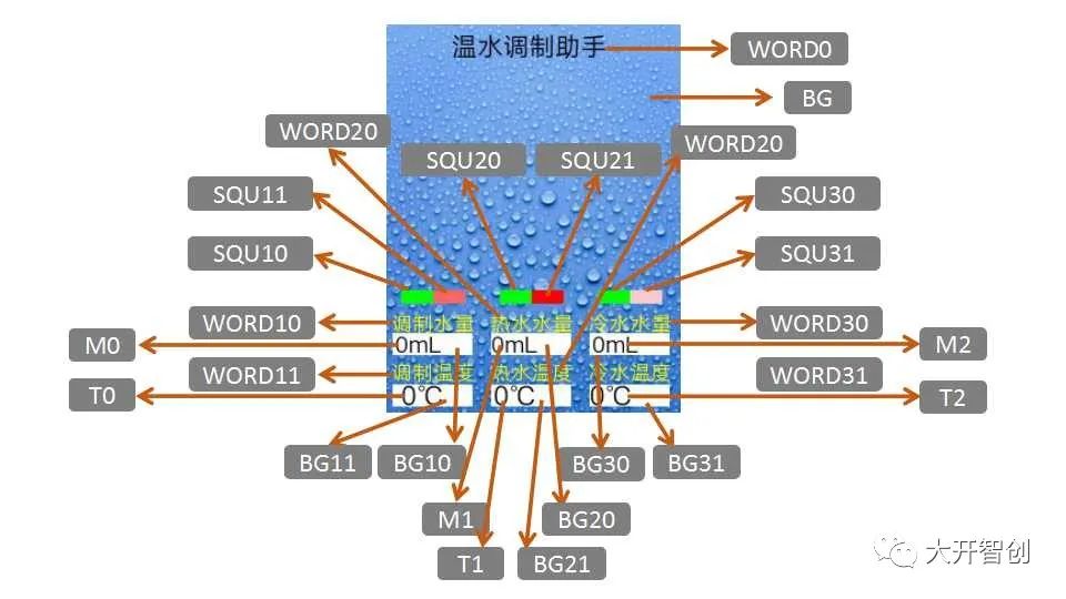
Figure 9
(6)Loop Execution Section
# Loop execution
while True:
    t_hot= ds1_hot.temp_c()    # Read the temperature value corresponding to ds1_hot, assign to variable t_hot
    t_cold = ds1_cold.temp_c()  # Read the temperature value corresponding to ds1_cold, assign to variable t_cold
    T1.config(text=(str(t_hot) + str("℃")))   # Update the hot water temperature value
    T2.config(text=(str(t_cold) + str("℃")))  # Update the cold water temperature value
    SQU21.config(h=(-2 * t_hot))    # Update the height of the rectangle corresponding to hot water temperature
    SQU31.config(h=(-2 * t_cold))   # Update the height of the rectangle corresponding to cold water temperature
    m_total= (10 * (round((numberMap(p_p21_analog.read_analog(), 4095, 0, 2, 20)))))            # Read the analog value of P21, map, round and multiply by 10, converting to an integer between 20-200, this value is the mixed water volume
    t_end= (2 * (round((numberMap(p_p22_analog.read_analog(), 4095, 0, 18, 30)))))              # Read the analog value of P22, map, round and multiply by 2, converting to an even number between 36-60, this value is the mixing temperature
    M0.config(text=(str(m_total) + str("mL")))  # Update the mixed water volume value
    SQU10.config(h=(-0.7 * m_total))           # Update the height of the rectangle corresponding to mixed water volume
    T0.config(text=(str(t_end) + str("℃")))  # Update the mixing temperature value
    SQU11.config(h=(-2 * t_end))             # Update the height of the rectangle corresponding to mixing temperature
    if (t_hot > t_end):
        calculation()  # When the hot water temperature is higher than the mixing temperature, call the calculation function to solve
time.sleep(0.3) # Wait for 0.3 seconds4.Structure Design and Processing
(1) Drawing Blueprints
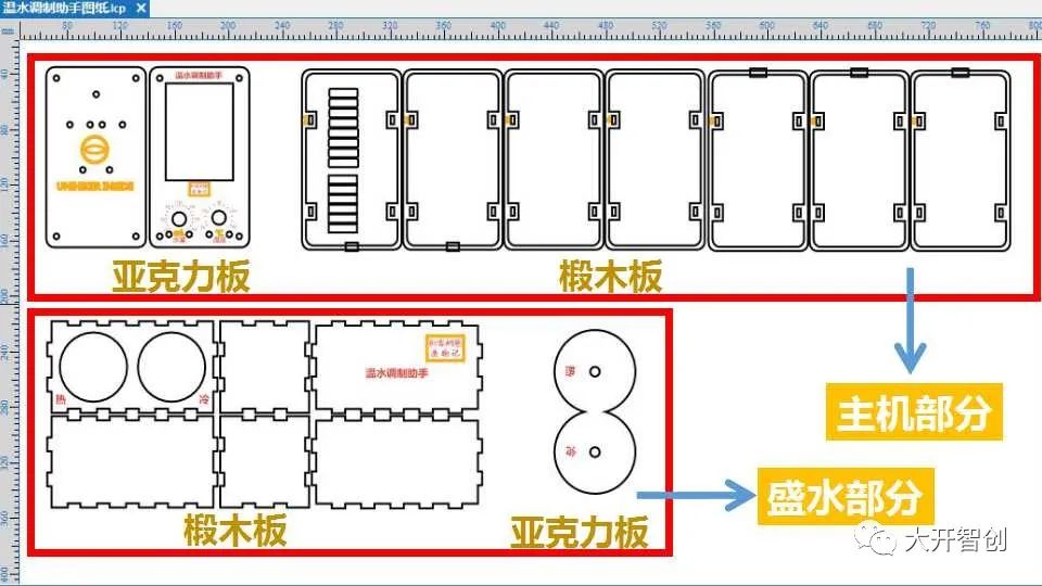
Figure 10
Using LaserMaker software to draw structural and modeling blueprints (Figure 10). The main unit part is designed to resemble a mobile phone shape, with the panel and bottom plate made of acrylic material, and the sides formed by multiple layers of linden wood frames; the water-holding part is a rectangular box with two round openings to hold two measuring cylinders, and a fixing device for the temperature probe is also designed.
(2) Cutting and Processing
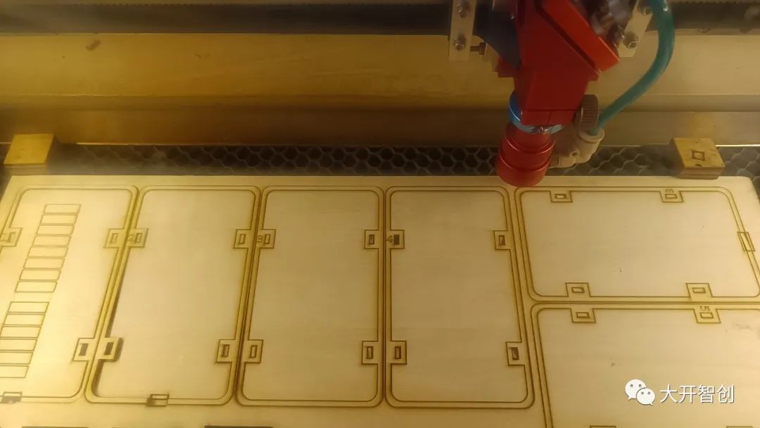
Figure 11
Using a laser cutter to cut linden wood and acrylic materials (Figure 11), the processing techniques used include cutting, shallow engraving, and line drawing. All cut parts are shown in Figures 12 and 13.
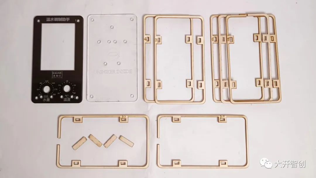
Figure 12
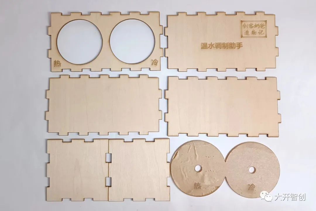
Figure 13
5.Product Assembly
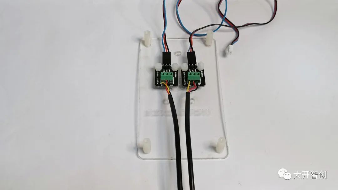
Figure 14
1. Fix the DS18B20 temperature sensor to the bottom plate; install dual-channel nylon pillars at the four corners of the bottom plate (Figure 14)
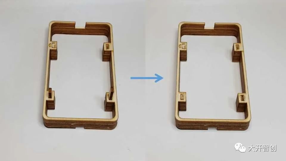
Figure 15
2. Stack the seven side components neatly and nail in four wooden wedges to make them one piece (Figure 15)
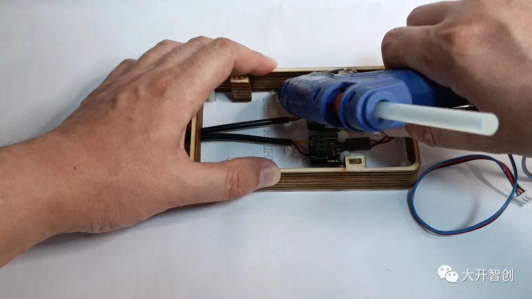
Figure 16
3. Use hot melt glue to bond the side frame and the bottom plate together (Figure 16)
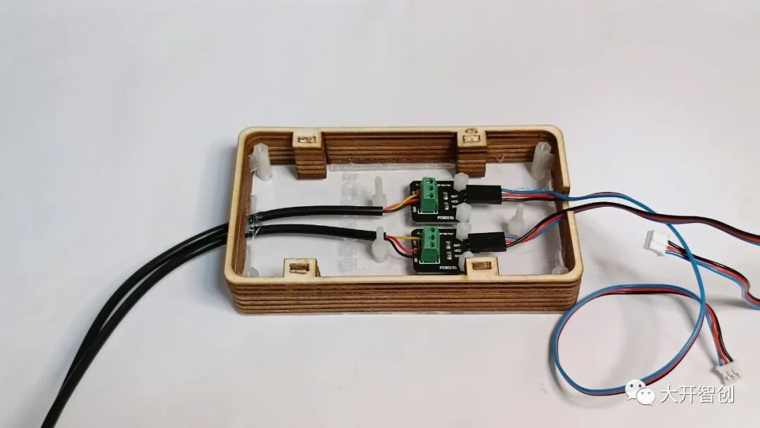
Figure 17
4. Insert three long screws from the bottom to the top on the bottom plate, without tightening the nuts, leaving a slight gap (Figure 17)

Figure 18
5. Place the Airborne Board on top and screw the three screws on the bottom plate into the screw holes on the back of the Airborne Board (Figure 18)
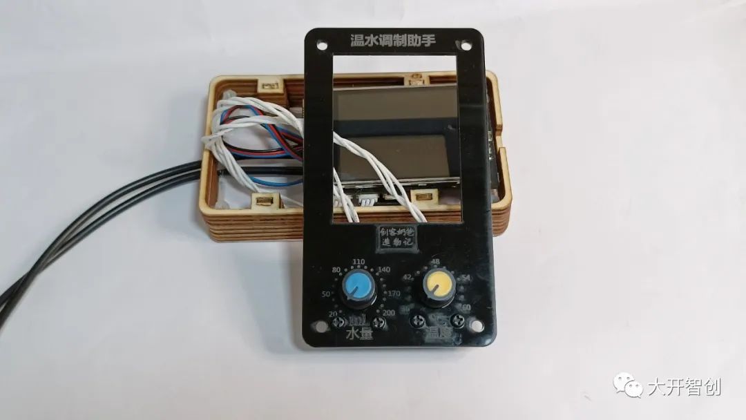
Figure 19
6. Install the knob potentiometers on the panel (Figure 19)
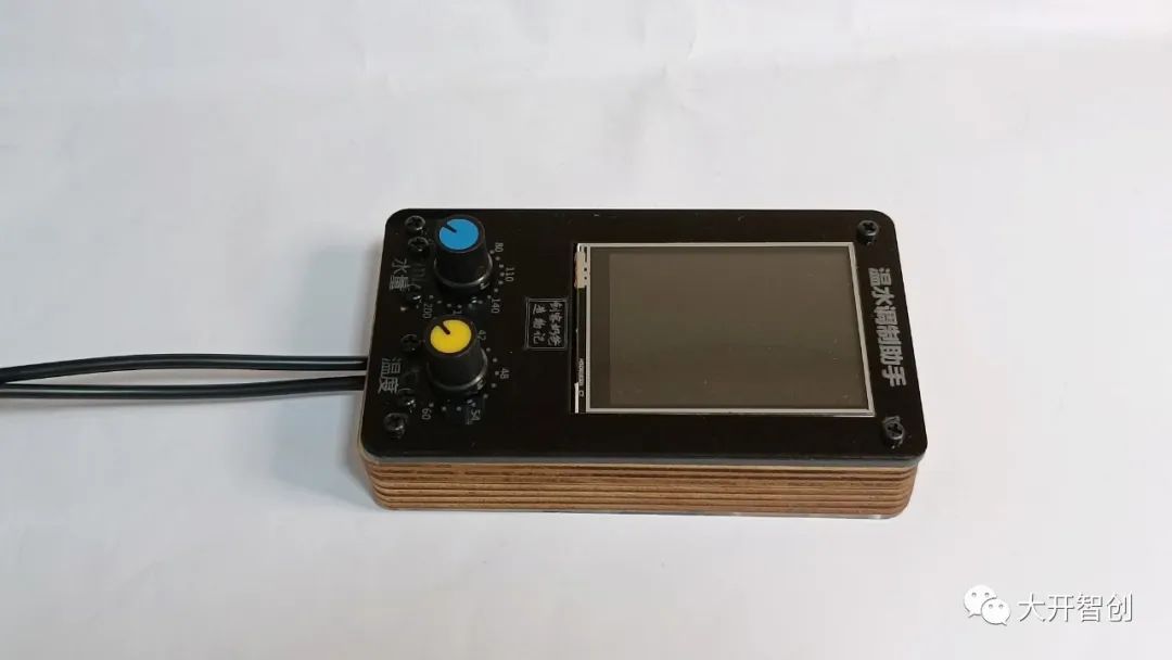
Figure 20
7. Close the panel and insert four screws into the screw holes to connect and secure with the dual-channel nylon pillars (Figure 20)
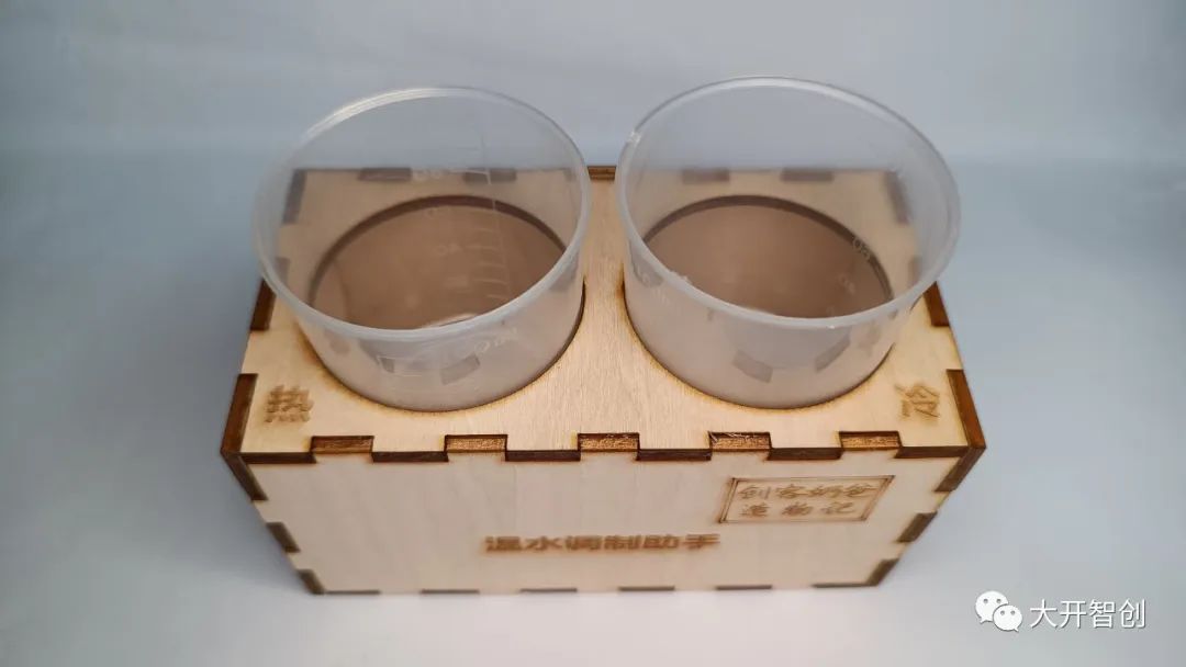
Figure 21
8. Assemble the water-holding box (Figure 21)
Figure 22
9. Place two small measuring cylinders inside (Figure 22)
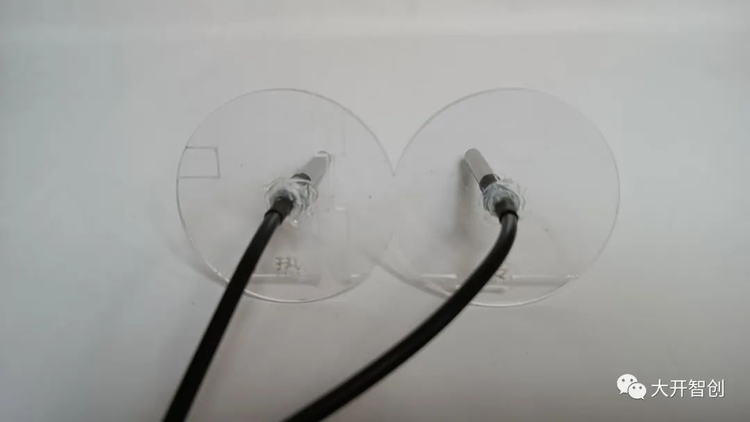
Figure 23
10. Fix the metal probe of the DS18B20 onto the 8-shaped board (Figure 23)
6.Debugging and Optimization
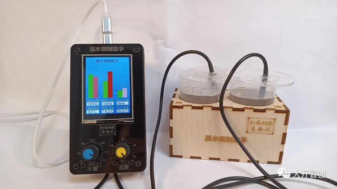
Figure 24
Pour hot and cold water into the measuring cylinders to test whether the device works properly (Figure 24). During the testing process, first check whether the temperature measurement function is normal; then rotate the knobs and observe whether the mixing water volume and mixing temperature can change accordingly in a timely manner; continuously change the mixing water volume and mixing temperature and observe whether the corresponding hot and cold water amounts can be calculated accurately and timely; check the display effect of the user interface.
Timely record any issues discovered during the testing process, analyze them, and resolve them by modifying the program to achieve all intended functionalities.
【Summary and Reflection】
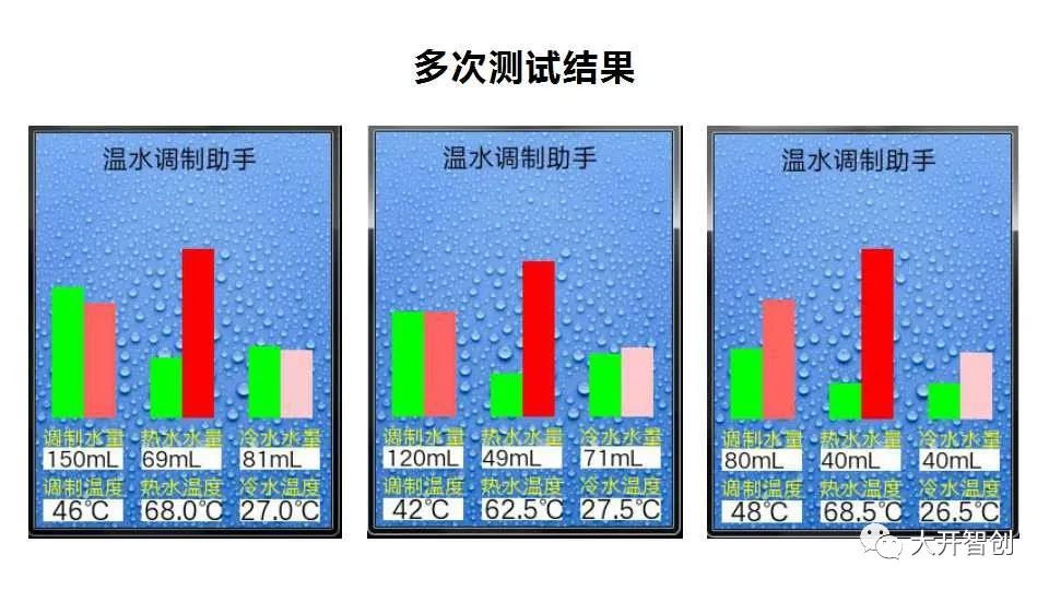 Figure 25
After multiple tests, I feel that this device runs well and is a relatively perfect maker project. However, there are still some areas that need improvement.
The DS18B20 temperature sensor used in this project has a maximum display temperature of 85℃, which makes it inadequate for this project since the temperature of boiling water is 100℃. Even the water in a thermos stays above 85℃ for a long time. Therefore, if it is to be used for real, a different temperature sensor will need to be swapped in.
Using a main control board with integrated I/O interfaces allows for a more refined and compact design without needing additional expansion boards. If 3D printing technology is combined with laser cutting to complete the modeling and structural design of this project, I believe it would be even better. Of course, that would take more time.
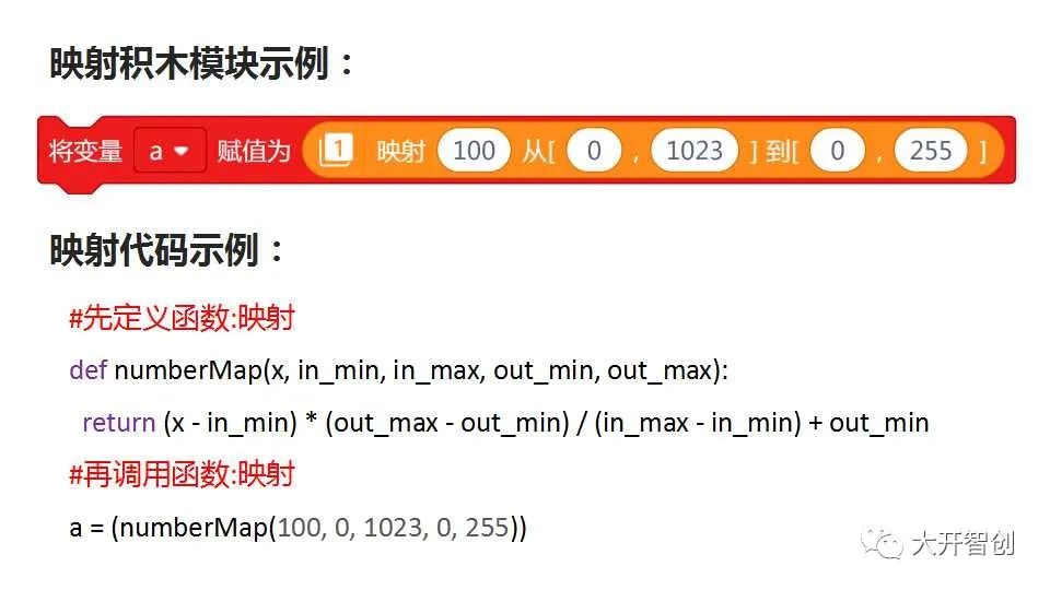
This is my first time using Python code to create a project. I encountered many difficulties along the way, but ultimately completed the task through research, tutorials, and comparing graphical commands. It has been a rare learning journey! Using code programming allows us to see deeper aspects, such as the “mapping” block in a graphical programming environment (figure), which can be completed by dragging and filling in five parameters; whereas in a pure coding environment, one must understand its algorithm, write functions for it, and then call them. In today’s growing trend of learning Python, as a maker educator, it is essential to keep up with the times!
This article is sourced from: DFRobot Maker Community
Author: Huai Ruogu

Recommended Reading:
-
Airborne Board Speedometer
-
【Highlights】 Airborne Board Remote Control IoT Car
-
Second