1. Circuit Completion Plan
In the previous chapter, we identified the circuit modules required for the smart faucet. Next, we will determine how these circuit modules connect to form a complete “system”.
Since our system structure is simple and the components are relatively few, it can be roughly divided into three parts:
• Power supply & charging part
• Main control part
• Drive & motor part
The following will design and explain each of the three parts sequentially.
(1) Power Supply & Charging Part
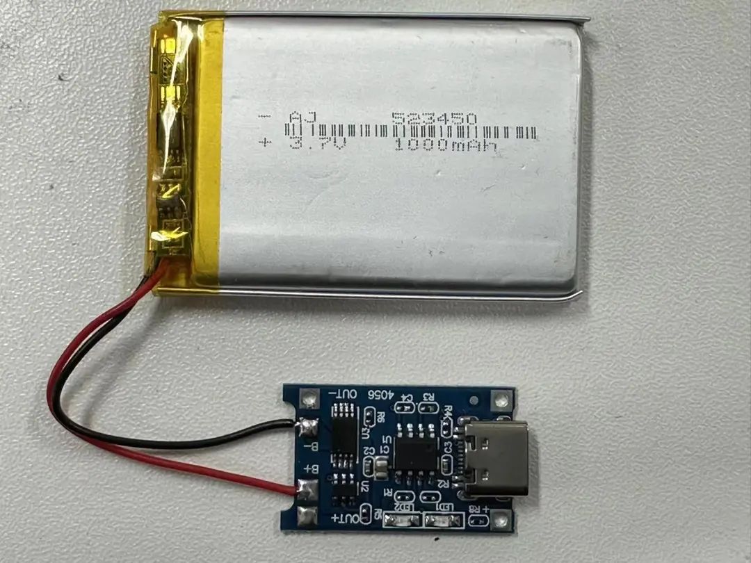
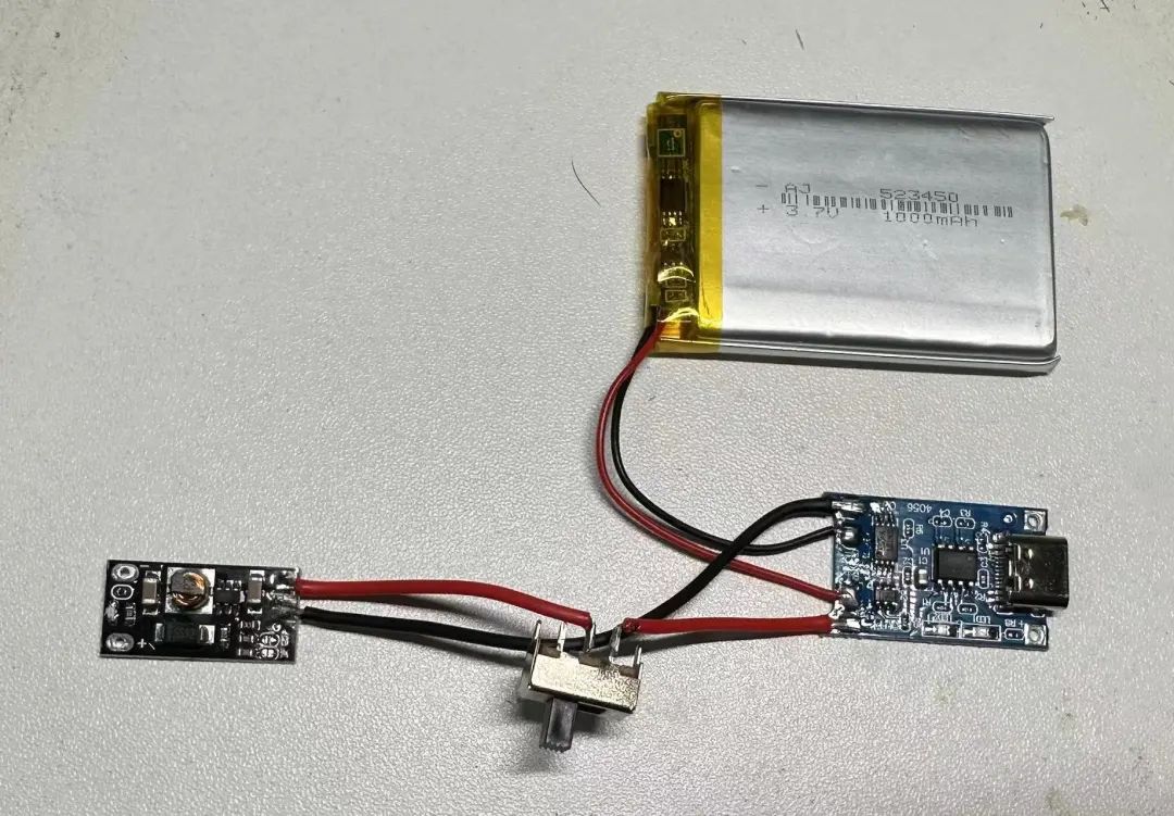
Step 1: Connect the TP4056 module to the battery.
TP4056 charging management chip is a commonly used constant current/constant voltage linear charging management chip for single-cell lithium batteries.
In short, it stops charging when the battery voltage exceeds the preset maximum voltage and stops discharging when it falls below the preset minimum voltage, achieving battery charge and discharge functionality.
This module also has an overcurrent protection function, stopping discharge immediately if the current exceeds 1A (charging can resume).
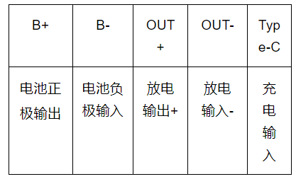
TP4056 Module Pin Definition
Wiring: The red wire (positive) of the battery connects to B+ of the TP4056 module, and the black wire (negative) connects to B-.
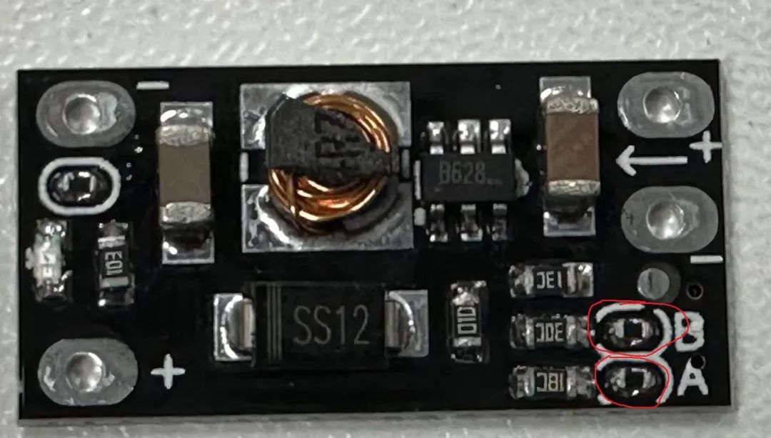
Step 2: Connect the boost board.
You only need to purchase a boost board that can raise the voltage from around 3.7V to 5V.
Note: This boost board defaults to 12V output upon arrival; you need to remove the two resistors A and B at the bottom right to output 5V.
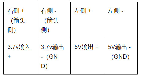
Boost Board Pin Definition
Wiring:
1. Connect the OUT+ of the TP4056 module to the right side + (arrow side) of the boost board, and the middle wire is disconnected to connect to the switch.
2. Connect the OUT- of the TP4056 module to the right side – (arrow side) of the boost board.
Note: The switch connects to the positive wire!
Step 3:
Close the switch and test whether the voltage at the left two ports of the boost board is 5V. If not, check for solder residue on resistors A and B of the boost board.
(2) Main Control & Sensor Part
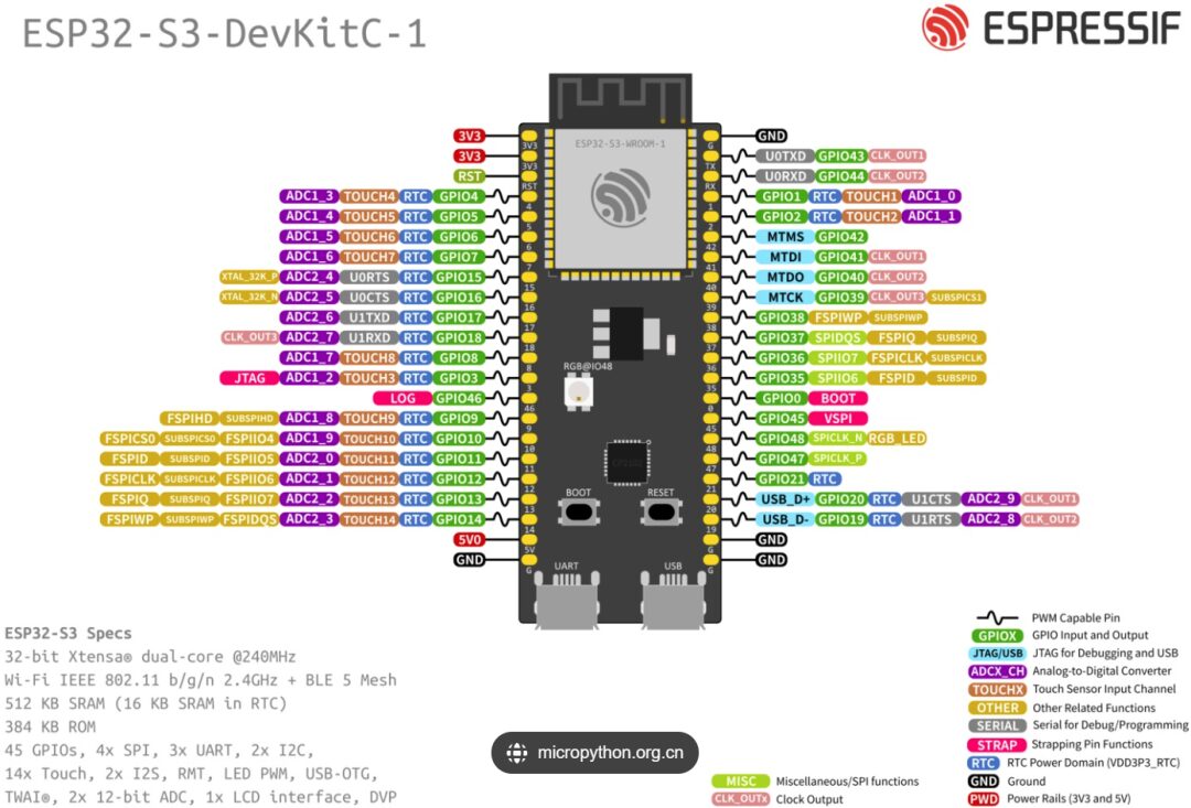
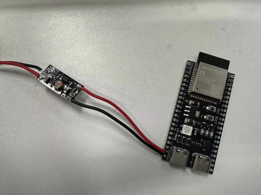
Step 1: Connect the ESP32S3 to the boost board.
Wiring:
1. Connect the 5V of the ESP32 to the left side + of the boost board.
2. Connect the GND of the ESP32 to the left side – of the boost board.
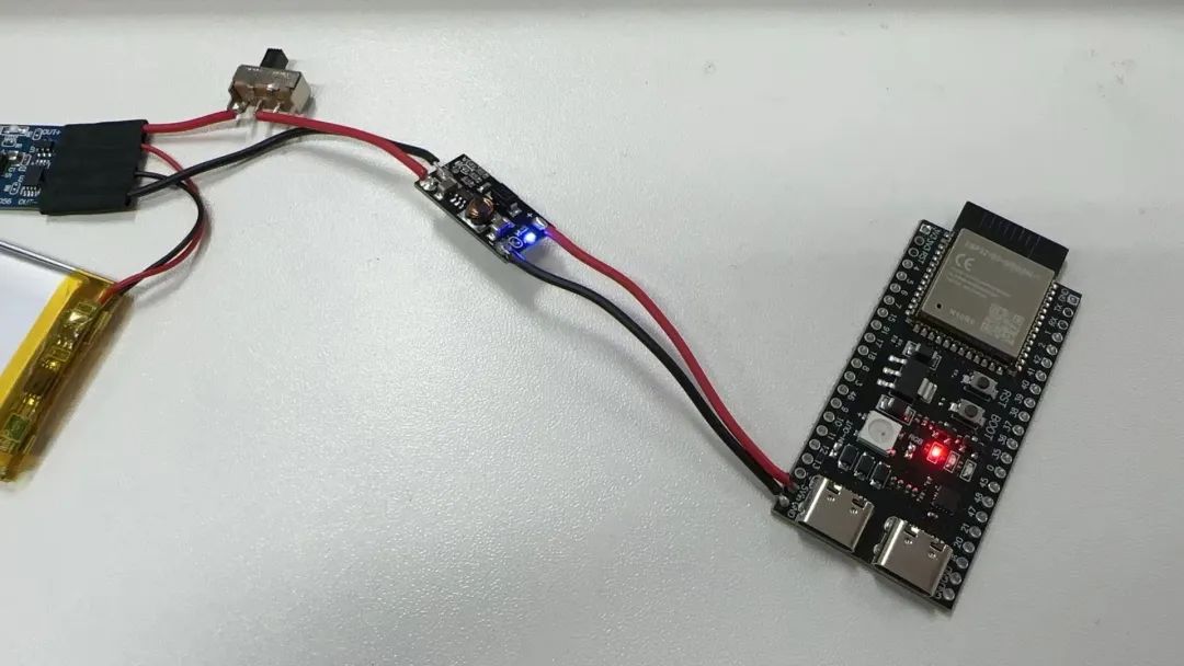
Step 2: Close the switch and test if the ESP32 powers on normally.
Step 3: Connect the FSR402 film pressure sensor to the voltage conversion module.
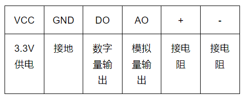

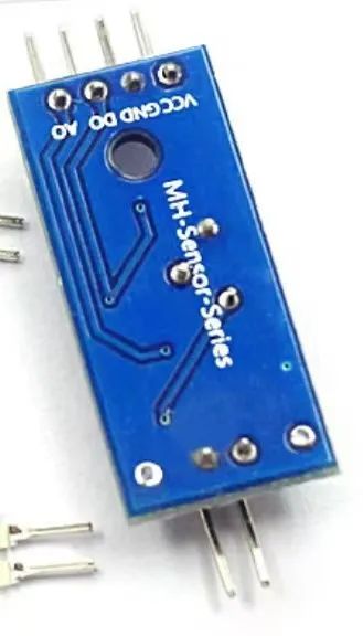
Wiring:
1. Connect the film sensor to the voltage conversion module + and – (the film sensor does not distinguish between positive and negative).
2. Connect VCC to the ESP32 3.3V pin, GND to the microcontroller GND pin.
3. Connect AO to pin 5 of the ESP32.
(3) Motor & Drive Part
Step 1: Connect the motor to the motor driver.
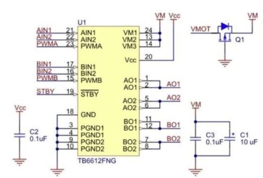
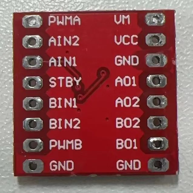
TB6612 Schematic Diagram
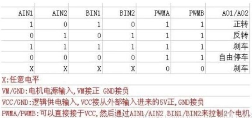
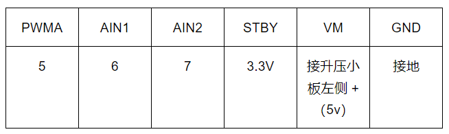
TB6612 Pin Usage Example Table
The main pin functions of TB6612FNG: (1) AIN1/AIN2, BIN1/BIN2, PWMA/PWMB are control signal input terminals; (2) AO1/AO2, B01/B02 are two motor control output terminals; (3) STBY is the control pin for normal operation/standby state; (4) VM (3-13.5 V) and VCC (2.7-5.5 V) are the motor drive voltage input and logic level input terminals, respectively.
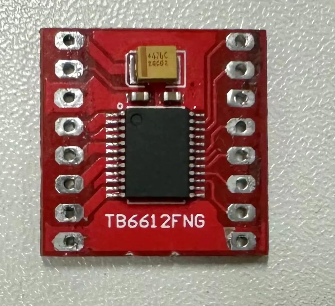
Wiring: One end of the motor connects to AO1, the other end connects to AO2.
Step 2: Connect the ESP32 to the motor driver, and connect the power supply part to the motor driver.
Wiring:
2. ESP32 Remote Control Code Design
The complete code is as follows:
#include <WiFi.h>#include <PubSubClient.h>
const char* ssid = "809";          // WiFi SSID
const char* password = "809809809";  // WiFi password
const char* mqttServer = "192.168.137.20";  // MQTT server address
const int mqttPort = 1883;                    // MQTT server port
const char* mqttTopic = "slt";                 // MQTT subscription topic
const int AI1 = 4;  // Control pin
const int AI2 = 5;  // Control pin
const int outputPin = 6;
const int pwmFrequency = 1000;  // PWM frequency in Hertz
const int pwmResolution = 8;    // PWM resolution, range from 1-16
WiFiClient espClient;
PubSubClient client(espClient);

void setup() {  //pinMode(outputPin, OUTPUT);  // Set pin as output mode  Serial.begin(9600);  // Connect to WiFi  WiFi.begin(ssid, password);  while (WiFi.status() != WL_CONNECTED) {    delay(1000);    Serial.println("Connecting to WiFi...");  }  Serial.println("Connected to WiFi!");
  // Connect to MQTT server  client.setServer(mqttServer, mqttPort);  client.setCallback(callback);  while (!client.connected()) {    if (client.connect("ESP32Client")) {      Serial.println("Connected to MQTT server!");      client.subscribe(mqttTopic);    } else {      Serial.print("MQTT connection failed, rc=");      Serial.print(client.state());      Serial.println(" Retrying...");      delay(2000);    }  }  ledcSetup(0, pwmFrequency, pwmResolution);  // Initialize PWM channel  ledcAttachPin(outputPin, 0);                // Associate pin with PWM channel  ledcWrite(0, 254);                          // Set PWM duty cycle to 50%  pinMode(AI1,OUTPUT);  pinMode(AI2,OUTPUT);}

void loop() {  if (!client.connected()) {    reconnect();  }  client.loop();}

void callback(char* topic, byte* payload, unsigned int length) {  // Convert received message to string  String message = "";  for (int i = 0; i < length; i++) {    message += (char)payload[i];  }  Serial.print("Received message: ");  Serial.println(message);
  // Control pin level based on message content  if (message == "1") {    digitalWrite(AI1, HIGH);    digitalWrite(AI2, LOW);    Serial.println("Set outputPin HIGH");    delay(1000);    digitalWrite(AI1, LOW);  } else if (message == "0") {    digitalWrite(AI2, HIGH);    digitalWrite(AI1, LOW);    Serial.println("Set outputPin LOW");    delay(1000);    digitalWrite(AI2, LOW);  }}

void reconnect() {  while (!client.connected()) {    if (client.connect("ESP32Client")) {      Serial.println("Connected to MQTT server!");      client.subscribe(mqttTopic);    } else {      Serial.print("MQTT connection failed, rc=");      Serial.print(client.state());      Serial.println(" Retrying...");      delay(2000);    }  }}
The following will analyze each segment of the program:
It includes preprocessor directives for the libraries WiFi.h and PubSubClient.h, which are used for handling WiFi connections and MQTT protocol communications.
#include <WiFi.h>#include <PubSubClient.h>It defines the credentials and parameters needed to connect to WiFi and the MQTT server, as well as configurations related to PWM (Pulse Width Modulation) and GPIO pin operations.
const char* ssid = "809";          // WiFi SSID
const char* password = "809809809";  // WiFi password
const char* mqttServer = "192.168.137.20";  // MQTT server address
const int mqttPort = 1883;                    // MQTT server port
const char* mqttTopic = "slt";                 // MQTT subscription topic
const int AI1 = 4;  // Control pin
const int AI2 = 5;  // Control pin
const int outputPin = 6;
const int pwmFrequency = 1000;  // PWM frequency in Hertz
const int pwmResolution = 8;    // PWM resolution, range from 1-16
WiFiClient espClient;
PubSubClient client(espClient);
In the setup function, serial communication is initialized, the program connects to WiFi, and attempts to connect to the MQTT server. Additionally, the PWM channel is initialized, and GPIO pins are set as output modes.
void setup() { //pinMode(outputPin, OUTPUT); // Set pin as output mode Serial.begin(9600); ... ledcSetup(0, pwmFrequency, pwmResolution); // Initialize PWM channel ledcAttachPin(outputPin, 0); // Associate pin with PWM channel ledcWrite(0, 254); // Set PWM duty cycle to 50% pinMode(AI1,OUTPUT); pinMode(AI2,OUTPUT);}The loop function is responsible for reconnecting to the MQTT server when disconnected and continuously processing MQTT messages.
void loop() { if (!client.connected()) { reconnect(); } client.loop();}The callback function is called when an MQTT message is received. It converts the received message into a string and controls the GPIO pin levels based on the message content. The following will focus on analyzing the callback function.
void callback(char* topic, byte* payload, unsigned int length) This function defines a function named callback that takes three parameters:
○ char* topic: A pointer to a character array representing the MQTT topic of the received message.
○ byte* payload: A pointer to the data payload representing the content of the received message in byte form.
○ unsigned int length: Represents the length (in bytes) of the received data payload.
String message = "";for (int i = 0; i < length; i++) { message += (char)payload[i];}This loop converts the byte data pointed to by the payload pointer into characters one by one, concatenating them into the String object message, which ultimately contains the complete message content.
Serial.print("Received message: ");Serial.println(message);if (message == "1") { digitalWrite(AI1, HIGH); digitalWrite(AI2, LOW); Serial.println("Set outputPin HIGH"); delay(1000); digitalWrite(AI1, LOW);} else if (message == "0") { digitalWrite(AI2, HIGH); digitalWrite(AI1, LOW); Serial.println("Set outputPin LOW"); delay(1000); digitalWrite(AI2, LOW);}This part of the code outputs the received message content to the serial monitor via serial communication, controlling the levels of pins AI1 and AI2 based on the message content. If the message content is the string “1”, it sets AI1 to high (usually corresponding to 5V or 3.3V) and AI2 to low (usually corresponding to 0V), then prints a message to the serial monitor indicating that the output pin has been set to high. The program then pauses for 1000 milliseconds (1 second) before setting the AI1 pin back to low.
If the message content is the string “0”, it sets AI2 to high and AI1 to low, printing a message to the serial monitor indicating that the output pin has been set to low. The program also pauses for 1000 milliseconds before setting the AI2 pin back to low.
The reconnect function attempts to reconnect to the MQTT server and subscribes to a topic upon success.
void reconnect() { while (!client.connected()) { if (client.connect("ESP32Client")) { Serial.println("Connected to MQTT server!"); client.subscribe(mqttTopic); } else { Serial.print("MQTT connection failed, rc="); Serial.print(client.state()); Serial.println(" Retrying..."); delay(2000); } }}

↑ Hot course, limited time coupon! 🎉 Grab it quickly ↑