Regarding the reference voltage of the ADC, I have found that many engineers do not have a clear understanding. This is especially true in scenarios where the battery directly powers the MCU and the ADC is used. This article provides a brief summary.
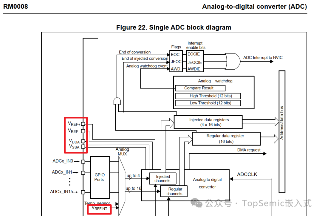
Taking the classic STM32F103 as an example, the reference voltage for the ADC is input through the external pins VREF+/VREF-. For some models with 64 pins or fewer, VREF+ is internally connected to the VDDA signal line and is not brought out of the chip; in this case, the ADC reference voltage is VDDA.
When the ADC reference voltage is stable and unchanged, normal collection and calculation can proceed. However, when the reference voltage changes, if the previous reference voltage is still used, it will lead to measurement errors since the new reference voltage value cannot be directly obtained.
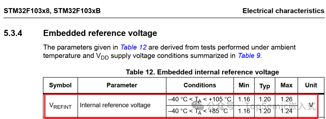
What should be done in this case? The internal reference voltage VREFINT of the chip can be utilized; it is a relatively fixed voltage, typically 1.20V.
It is internally connected to ADC channel 17. If the accuracy requirement for ADC measurement is not very high, VREFINT can be considered as a fixed 1.2V. At this point, by reading the value of this channel REFINT_DATA, the current ADC reference voltage can be deduced. Because 1.2V = VREF_ADC * REFINT_DATA / FULL_SCALE
Thus, VREF_ADC = 1.2V * FULL_SCALE / REFINT_DATA, where FULL_SCALE is 4095 (ADC resolution 12bit).
Using the deduced reference voltage value, the actual ADC measurement value can be calculated.
Vchx = VREF_ADC * ADCHX_DATA / FULL_SCALE = 1.2V * (ADCHX_DATA / REFINT_DATA).
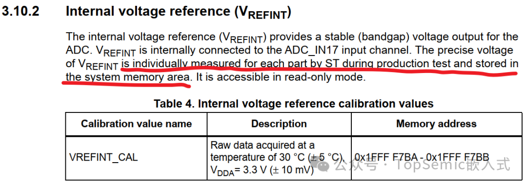
However, in reality, there will be differences in VREFINT between individual chips. If higher accuracy is required, calibration methods can be employed:
When VDDA is stable at 3.3V, the value of the VREFINT channel can be collected through the ADC, denoted as REFINT_CAL. This way, the accurate VREFINT voltage for each chip can be obtained. In practical use, REFINT_CAL needs to be stored in the MCU Flash for future use. Then, the ADC measurement value can be calculated according to the above method (i.e., first read ADC channel 17 to deduce the current actual reference voltage, then read the actual channel value to calculate the ADC measurement value).
Vchx = (3.3V * REFINT_CAL / FULL_SCALE) * (ADCHX_DATA / REFINT_DATA).
This method increases the workload for users because the STM32F103 is an older product from many years ago and does not have factory calibration. Later products like the STM32F030 have already undergone the aforementioned calibration at the factory, allowing users to use them directly.
At this point, you may be curious about what this internal reference voltage actually is; it is called the Bandgap voltage. The MCU’s Bandgap voltage is a highly stable voltage reference source, typically generated by the Bandgap Reference Circuit within the integrated circuit. The Bandgap circuit utilizes the positive and negative temperature coefficients of bipolar transistors to cancel each other out, generating a voltage that is almost unaffected by temperature changes (the typical value is about 1.2V, with specific values varying based on process and design).
Having said all this, the internal Bandgap voltage is not the direct reference voltage source for the ADC. It is merely used to deduce the actual reference voltage value. This method also has certain limitations, as it requires the ADC to first collect the Bandgap channel voltage and then the actual channel voltage. If there is a sudden change in the reference voltage during this collection process, the converted value will also be inaccurate because the deduced reference voltage has already changed. However, the likelihood of this situation occurring is relatively small, and for most scenarios, this method works fine.
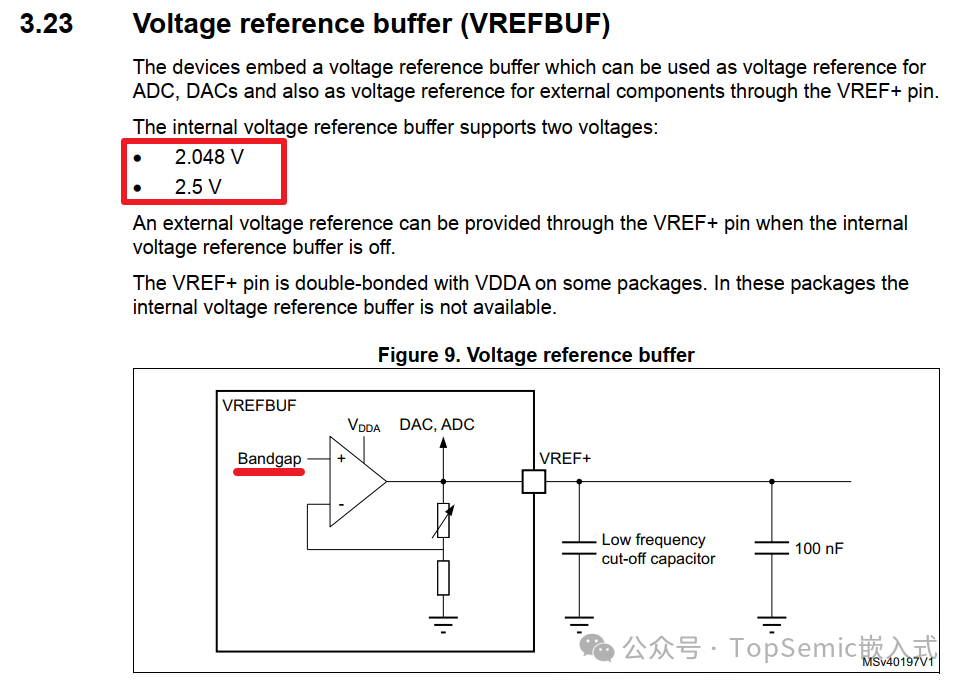
Some MCUs have an internal voltage reference source, such as the STM32L5, which is called VREFBUF.
It can support two voltages, 2.048V and 2.5V, which can be directly used as the ADC reference voltage.
The reference source still comes from the Bandgap voltage, generating different output levels through a voltage divider circuit. As shown in the block diagram below, due to the virtual short characteristics of the operational amplifier, the negative input of the operational amplifier is equal to the voltage of the positive input (Bandgap reference voltage). The voltage divider resistors on the right adjust the division ratio to make the VREFBUF output voltage reach the set level. When using this function, be aware that the Vref+ pin must be occupied and connected to the ground capacitor; otherwise, this reference voltage cannot be generated.
The deviation of VREFBUF is relatively small, as described in the manual:
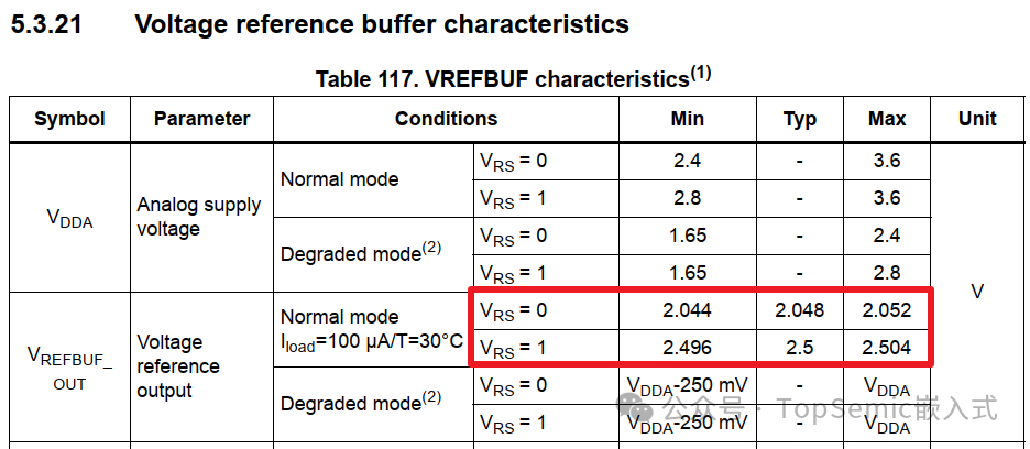
Using VREFBUF is much more convenient; you only need to collect the required channel. It is important to note that the collected voltage value must not exceed the VREFBUF voltage value. For example, if the collected voltage value is 3V, then it needs to be collected after voltage division.
Of course, if the external reference voltage of the ADC in the system is already very stable, then none of the above introductions are necessary.。
Sharing several practical debugging components for Keil

Sharing a lightweight C language library for Modbus

Analyzing MCU stack space through case studies