1 Description in the JTAG Standard
Latest JTAG standard: IEEE_std_1149.1-2001
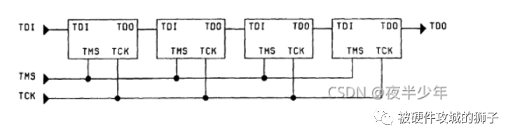
Figure 1 JTAG Principle
1.1 TMS
TMS is the start enable signal (Standard PAGE-11), pull-up:
1.2 TCK
TCK is the clock signal (Standard PAGE-9) effective on the rising or falling edge, can be pulled up or pulled down, depending on specific device requirements:
1.3 TDI
TDI is the data input (Standard PAGE-11), pull-up:
1.4 TDO
TDO is the data output (Standard PAGE-12), tri-state output, can be cascaded with TDI, pull-up or floating:
1.5 TRST
TRST is the reset signal (Standard PAGE-13), low level for reset state, pull-up:
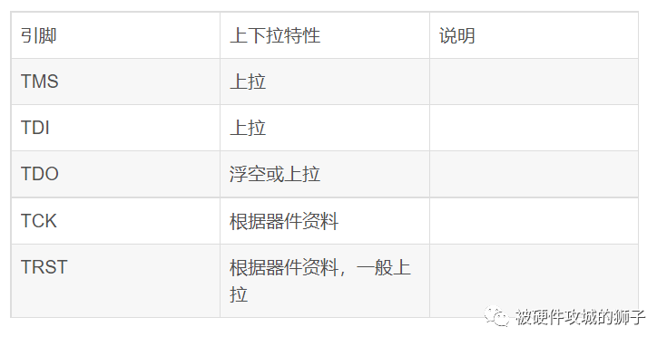
3 Summary (Determine based on the data sheet)
Pull-up and pull-down circuits are generally already implemented internally in the IC, external addition is not necessary. If added externally, it must be consistent with the pull-up and pull-down characteristics in the IC manual. The TCK and TRST pins may differ, while TDI and TMS are both pull-up. TDO is usually floating within the IC, and since TDO is connected to TDI, a pull-up can be added to match TDI.