1. Introduction to the Logic Converter Control Panel
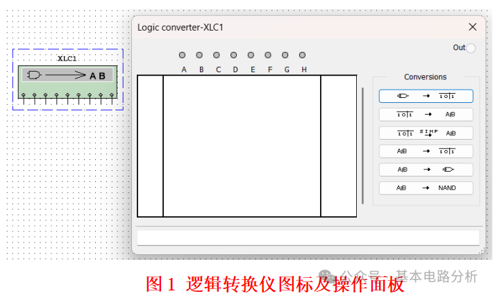
For complex logical relationships, the manual conversion workload between various representations (truth tables, logical expressions, logical circuits) is relatively large. The Logic Converter (Logic Converter) can quickly complete various conversions. Its icon (XLC1) has a total of 9 ports, from left to right, there are 8 input ports (A~H) and 1 output port (Out). The control panel provides a Conversions section with 6 buttons, which from top to bottom complete: Circuit to Truth Table; Truth Table to Expression; Truth Table to Simplified Expression; Expression to Truth Table; Expression to Gate Circuit; Expression to NOR Gate Circuit. The left side of the control panel has a blank area for the truth table, which can be manually edited or automatically generated, and can display all logical variable input combinations and corresponding output function values. The bottom blank area can display the current truth table corresponding to the logical expression.
2. Conversion Operation Example
Requirement Design a 3 -person voting machine, with 3 inputsA,B,C, having 2 or more inputs equal to 1 will outputY=1.
① From “ Truth Table” to “ Logical Expression”
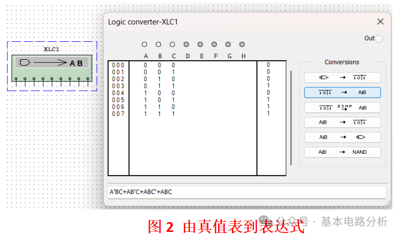
Left-click on the three gray circular holes corresponding to A, B, and C on the Logic Converter control panel, the corresponding holes will turn white, automatically generating an 8-row truth table, but each row’s variable corresponding logical function value is “ˣ.” Left-click on the corresponding row’s “ˣ,” it can be modified to “0” or “1, according to the majority voting machine’s requirements, set the truth table variable values for 011, 101, 110, 111 to 1, and other variable values to 0, thus obtaining the truth table for the 3-person voting machine as shown in Figure 2. Click the second row button in the conversion area, and the logical expression will be obtained at the bottom of the control panel as “A’BC+AB‘C+ABC’+ABC.” Clearly, this expression is not the simplest expression. If you want to obtain the simplest expression, click the third row button in the conversion area, and the simplest expression will be “AB+BC+AC.”
② From “ Logical Expression” to “ Logical Circuit”
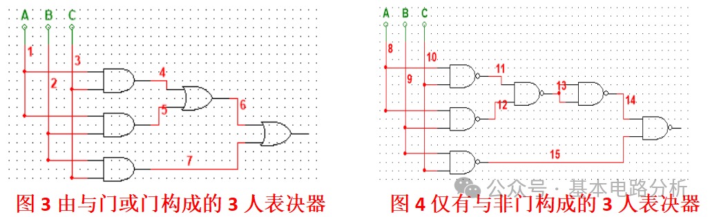
The expression can be obtained from the truth table, or the expression can be manually inputted. When manually inputting the logical expression, pay attention to the syntax, using “ *” to represent AND, “+” to represent OR, “‘” to represent NOT, in the blank area at the bottom of the Logic Converter control panel, input “ A*B + A*C + B*C” or “AB + AC + BC” ( Multisim supports omission of* symbol); click the sixth row button in the conversion area, and you can obtain the logic circuit composed of AND and OR gates as shown in Figure 3. If you click the seventh row button in the conversion area, you can obtain a circuit composed only of NOR gates as shown in Figure 4..
③ From “ Logical Circuit” to “ Truth Table”
In the Multisim workspace, build any logical circuit, for example, using AND, OR, and NOT gates to form a complex logical circuit, with input ports asA,B,C,D, and output port as Y, connect the input ports of the logical circuit to the corresponding ports of the Logic Converter, and connect the output port Y of the logical circuit to the “OUT” port of the Logic Converter, click the first row button in the conversion area, the Logic Converter will automatically analyze the circuit, listing the truth table in the display area, and readers can experience it themselves.
3. Precautions for Using the Logic Converter
① Number of input variables: The Logic Converter supports a maximum of 8 inputs (A~H), exceeding this will not work;
② Expression syntax: The NOT operation must use “ ‘”, cannot use “ ~” or “!,” AND operation can use “*” or omitted (e.g., AB= A*B), or OR operation uses “+” or OR; avoid syntax errors (e.g., mismatched parentheses, incorrect variable names);
③ Circuit generation limitations: The generated circuit may contain multiple gates, which can be simplified using Multisim’s “ Optimization” function (e.g., merging redundant gates).
With the Logic Converter, there is no need to manually draw a large number of truth tables or derive complex expressions, significantly improving the efficiency of digital circuit design!