Using the Logic Converter in Multisim for Digital Circuit Simulation
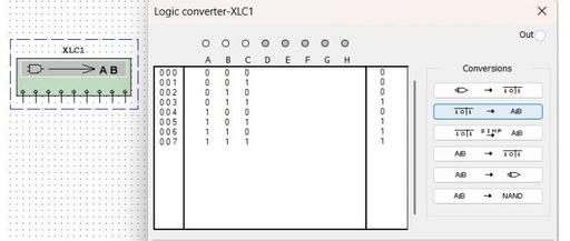
1. Introduction to the Logic Converter Control Panel For complex logical relationships, the manual conversion workload between various representations (truth tables, logical expressions, logical circuits) is relatively large. The Logic Converter (Logic Converter) can quickly complete various conversions. Its icon (XLC1) has a total of 9 ports, from left to right, there are 8 input … Read more