
We currently have standard techniques for generating negative output voltages and methods for dynamically adjusting output voltage. In this article, I will introduce the missing link between these two technologies—a level-shifting circuit that combines them.
Applications requiring negative output voltage include: testing and measurement, aerospace and defense, automotive, and medical. A common method to create a negative power rail is to use a traditional buck converter and operate it as an inverting buck-boost converter (References 1-3): connecting the ground pin of the buck converter integrated circuit (IC) to the negative output voltage (-VOUT) and connecting the inductor output to system ground (0V). Figure 1 is an example of this configuration, utilizing a resistor divider between the output and feedback (FB) pins to set the output voltage.
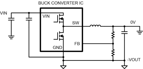 Figure 1: A buck converter generates negative output voltage when operated as an inverting buck-boost converter.
One major challenge of generating negative voltage using a buck converter IC is how to connect to the input and output signals and perform level shifting. The reference point for the input/output (I/O) pins is the negative voltage output (-VOUT), not the system ground (0V). This TI application report explains several circuits that can perform level shifting for enable (EN), power good (PGOOD), and synchronization (SYNC) signals between system ground (0V) and the IC local ground (-VOUT). The report also contains useful suggestions for testing the circuit by measuring the bode plot and load transient response. It includes several examples of level-shifting circuits.
Next, let’s look at dynamic voltage regulation. For traditional buck or boost converters, References 4, 5, and 6 demonstrate several methods for regulating output voltage. As shown in Figure 2, a popular method is to add a resistor between the FB pin and an adjustable voltage source (VADJ). By increasing or decreasing VADJ, the output voltage of the converter can be dynamically adjusted. When VADJ is above the voltage at the FB node (equal to the reference voltage VREF), current will flow through the resistor RADJ into the FB node, causing the output voltage to decrease.
Conversely, if the VADJ voltage is lower than the voltage at the FB node, current will flow in the opposite direction through the resistor RADJ, causing the output voltage to increase.
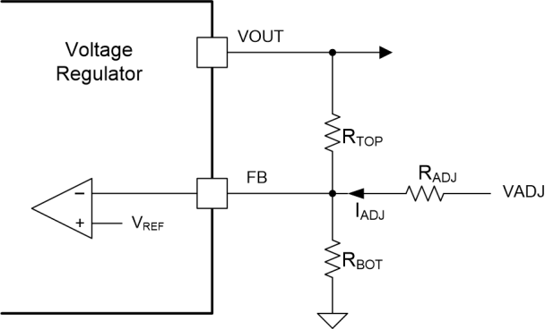 Figure 2: You can dynamically adjust the converter’s output voltage by controlling the current flowing into/out of the FB node.
A simple way to generate VADJ is by passing a pulse-width modulation (PWM) signal through a resistor-capacitor low-pass filter. The PWM signal can be output by a microcontroller or other digital chip. By controlling the duty cycle of the PWM signal, VADJ can be adjusted. Using this method to dynamically adjust the negative output voltage of an inverting buck-boost converter can be challenging since the local ground of the buck converter IC is connected to the output voltage (-VOUT), not the system ground (0V). This situation likely requires a level-shifting circuit, such as the connection with the I/O pins I mentioned earlier (Figure 3).
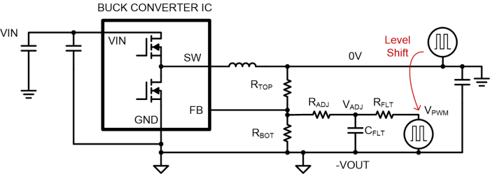 Figure 3: Using a grounded PWM signal to generate VADJ requires a level-shifting circuit.
Figure 4 shows an example of such a level-shifting circuit. This circuit converts a PWM signal from system ground (0V) to a PWM signal for IC ground (-VOUT). The PWM signal source controls the P-channel metal-oxide-semiconductor field-effect transistor (MOSFET) to turn on and off. When the P-channel MOSFET is on, it pulls the gate voltage of the N-channel MOSFET above the gate threshold voltage, turning on the N-channel MOSFET, which then pulls VPWM down to -VOUT. When the P-channel MOSFET is off, the N-channel MOSFET is off, and resistor RPU pulls VPWM up to VBIAS. VBIAS can be generated using a precision shunt regulator (e.g., Texas Instruments LM4040), which is connected to -VOUT and connected to VIN through a resistor. As shown in Figure 3, RFLT and CFLT act as a low-pass filter to generate VADJ. The output voltage can be adjusted by varying the current through RADJ.
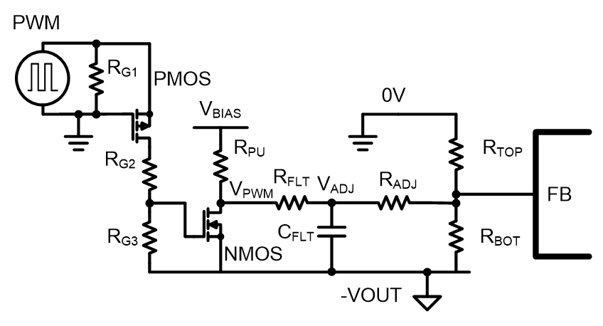 Figure 4: Example of a level-shifting circuit: using discrete components to convert the PWM signal from system ground to IC ground (-VOUT)
Simulation results in Figure 5 demonstrate that this method can be used to adjust negative output voltage while the buck converter is operating as an inverting buck-boost converter. In the first 6 milliseconds (ms), the negative output voltage (red marker, labeled “NVOUT”) slowly rises to -7V. The blue line represents VADJ, which follows the negative output voltage during startup. The PWM circuit is enabled at 7 ms (purple is the input waveform of the PWM), causing the PWM to generate a level shift (VPWM). VADJ (blue) rises, and the converter output voltage also increases. The converter reaches a new steady-state operating point (approximately -2V) after about 2 ms of transition time. In the simulation, adjusting the PWM signal can smoothly and effectively lower the output voltage.
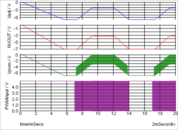 Figure 5: Simulation results demonstrate how to use a level-shifting circuit to dynamically adjust negative output voltage.
This method uses a simple circuit to achieve adjustable negative output voltage, which can be used with many off-the-shelf buck converter ICs. The circuit combines common techniques for output voltage regulation and signal level shifting. By using the level-shifting circuit introduced in this article, the PWM source at system ground can regulate the current at the power converter FB node. The main challenge of this design is to control the injected current while the IC’s ground voltage (which is the same as the negative output voltage) changes. This technique is applicable to various applications requiring dynamic adjustment of negative output voltage.
(Original Reference: Dynamically adjust negative output voltages)
Editor: Amy Guan