
Author / Crab Claw Facing Heaven
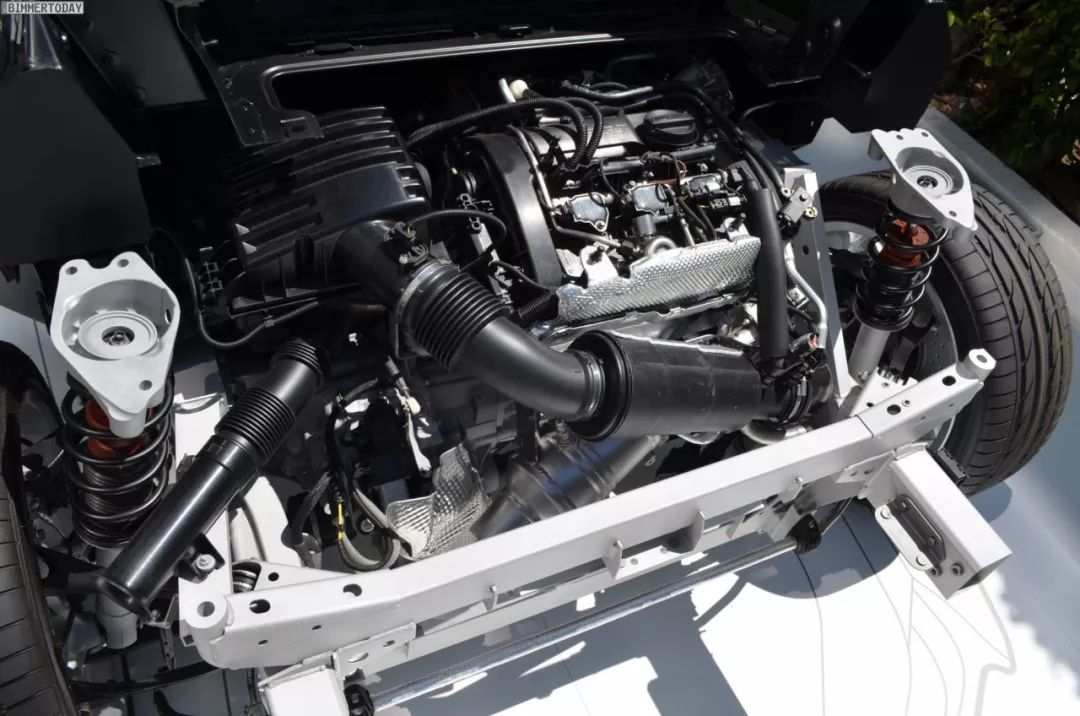
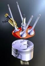
The Working Principle of Fuel Injectors in Most Vehicles During the period when fuel injection is needed, the valve body inside the injector is lifted under the control of electromagnetic force, opening the oil path between the internal high-pressure fuel and the nozzle, allowing high-pressure fuel to spray out from several nozzles.

Currently, most vehicles use a return-style fuel supply system, where the fuel rail pressure remains relatively constant after reaching the designed maximum value.
Therefore, the amount of fuel injected is mainly controlled by adjusting the injection duration. This leads to two issues:
-
At higher RPMs, the allowed injection duration is shorter, and the maximum allowable injection amount is smaller. -
During rapid fluctuations in fuel pressure, the fuel rail pressure may not stabilize at the designed maximum value.
Thus, the fuel injection amount is not primarily controlled by the length of the injection duration.
Generally speaking, the design margin of factory fuel injectors is about 20%. The size of this margin mainly considers factors such as atmospheric conditions, nozzle contamination, rich fuel correction, and different fuels.
Therefore, when increasing the target turbo pressure, enriching the target air-fuel ratio, or expanding the cylinder, the conventional fuel flow may increase, and the margin of the fuel injector may become insufficient, even failing to meet the normal fuel flow requirements of the factory fuel system.
Therefore, many vehicles require larger fuel injectors or an increase in fuel rail pressure to increase the maximum fuel amount when significantly enhancing power or expanding RPM.
Considering that ethanol fuel requires a richer air-fuel ratio than gasoline, a larger flow fuel injector may also be needed when switching to ethanol fuel.
Considering the potential contamination and blockage of fuel injectors in older engines, the original design margin of about 20% may not be sufficient, and at this time, the injectors should be cleaned.
When increasing the manifold pressure, the fuel rail pressure also needs to be proportionally increased to maintain fuel injection efficiency.
If layered control of fuel concentration is not considered, a more intuitive method is to observe the pulse width of fuel injection to determine whether the fuel injector can meet the current fuel flow demand.
At this time, attention should be paid to the impact of injector offset on the fuel amount.
Different models of fuel injectors have different offsets. Therefore, when replacing fuel injectors, it is important to check the manufacturer’s data and modify or re-establish the “injection offset/system voltage” correction map in the ECU to address this issue as much as possible.
Next, let’s briefly introduce the design of fuel injection methods from different brands
Suzuki Dual Injector
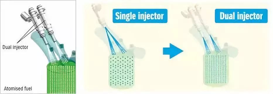
One injector is set for each intake valve , which allows the injector to be closer to the valve, resulting in better atomization and lower cylinder temperature, thus enabling a higher compression ratio.
Manifold Injector
Due to the low injection pressure in early engines, the fuel injector needs to be placed in the intake manifold to ensure that the injected fuel can mix thoroughly with the air before entering the cylinder.
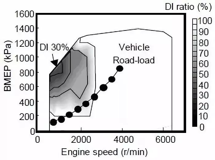
Stratified Combustion
It is commonly believed that the best combustion occurs at an air-fuel mass ratio of 14.7:1. However, to reduce fuel consumption, a more suitable approach is to increase the throttle opening (reduce pumping losses) and decrease fuel concentration at low engine loads.
In stratified fuel injection, the injector sprays an appropriate amount of fuel into the cylinder multiple times. Less fuel is injected at the beginning of the piston’s downward stroke, and more fuel is injected later, resulting in a concentration gradient where the fuel-air mixture is denser near the spark plug and more diluted farther away.
The fuel consumption advantage of stratified lean combustion is mainly evident at low loads, while its drawback is that excess oxygen can react with nitrogen under high temperature and pressure, producing NOx pollutants.
Mitsubishi GDI Engine
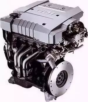
The GDI series engines began to be installed in vehicles in 1996, resulting in a 20%-35% reduction in fuel consumption and about a 20% decrease in carbon dioxide emissions. The lean fuel injection technology of GDI allows the air-fuel ratio to be as lean as 40:1 at low engine loads.
With the high-pressure injection system, GDI engines place the injectors inside the cylinder. During each intake stroke, fuel is injected twice, with the first injection reducing cylinder temperature, increasing VE, and suppressing knock tendency. Thus, the GDI engine has a compression ratio of 12.5:1.
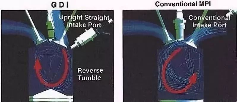
The relatively vertical intake valves and the concave piston tops create a good rolling motion in the cylinder, concentrating the fuel-air mixture near the top of the spark plug.
Renault IDE Combustion
Renault’s lean combustion primarily increases the proportion of EGR (Exhaust Gas Recirculation) (with three available ratios, maximum 25%). Most of the exhaust gas is nearly inert, lacking oxygen and fuel, but under rich fuel conditions, some usable fuel may still be present.
Increasing the intensity of EGR effectively reduces filling efficiency and weakens valve overlap. Therefore, at low loads, EGR intensity can be moderately increased to reduce fuel consumption.
How to ensure ignition with a high exhaust gas ratio? The IDE engine places the spark plug and injector (Siemens 100bar) very close together, with the spark plug directly in the fuel spray path.
One advantage of increasing EGR is that it can reduce intake resistance by utilizing the velocity of the exhaust gas. The downside is higher cylinder temperatures and weaker power output.
Alpha JTS Engine
The design direction of the JTS engine mainly focuses on increasing power. The 2.0 displacement engine produces 165 hp and 152 lb-ft of torque. It is mainly used in Alfa Romeo 1.9, 2.2, and 3.2 engines, with a compression ratio of 11.3:1.
Since its lean combustion state is only suitable for conditions below 1500 RPM, the valve angles of this series of engines are relatively flat, and the piston tops are also flat, allowing smoother intake.
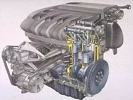
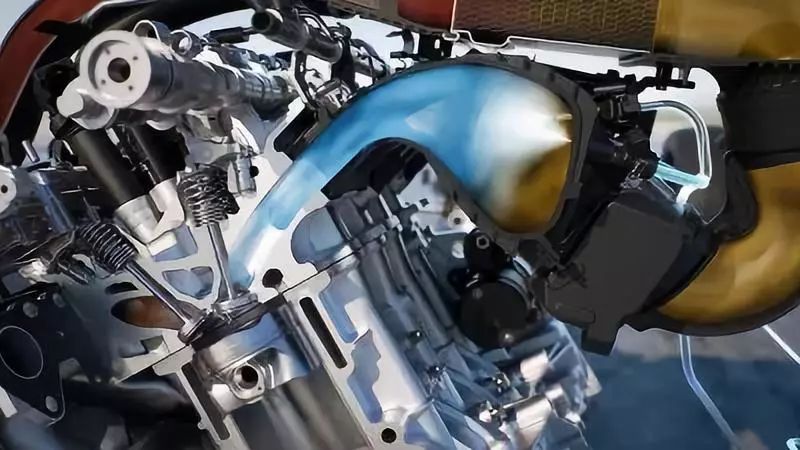
Mercedes-Benz CGI Engine
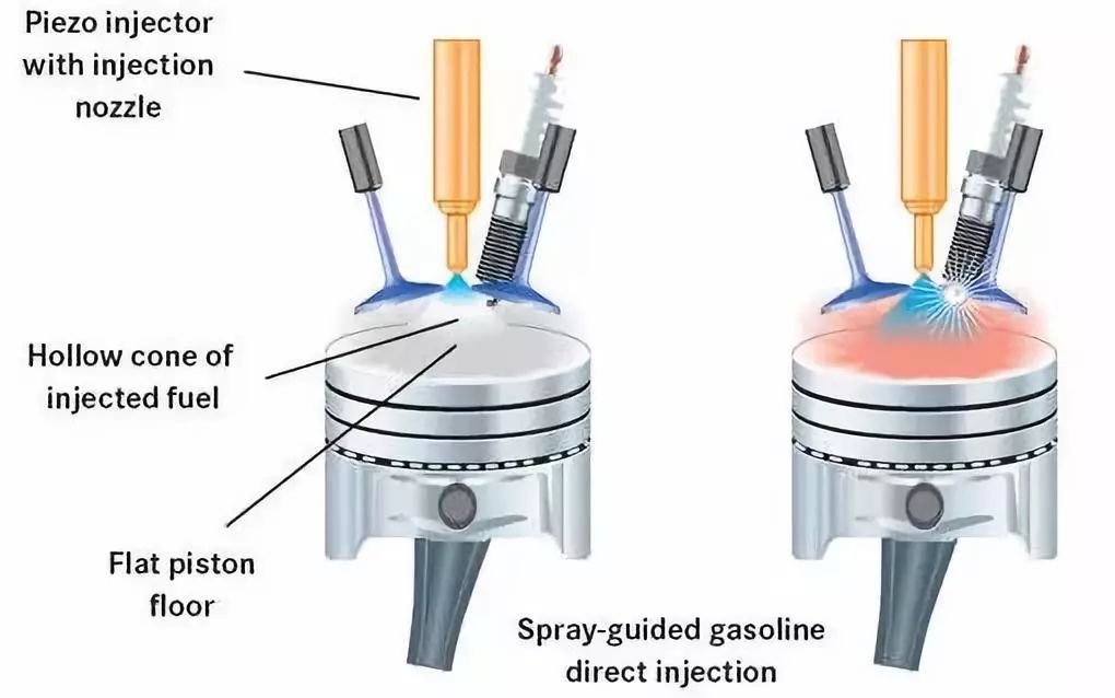
In conventional engines, the shape of the piston top is commonly used to guide the airflow and fuel mixture.
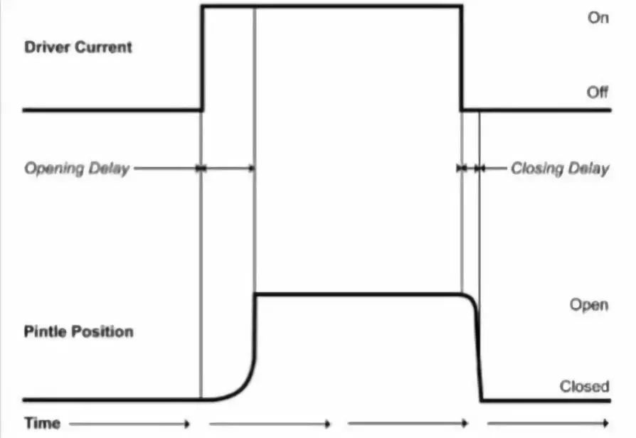
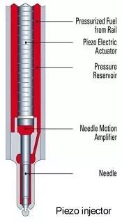
In the CGI engine, however, the guiding effect of the piston top is minimal. As shown in the diagram, the injector center has an expandable piezoelectric crystal and a movable needle ball structure. The volume of the crystal can be controlled through the circuit, thus controlling the expansion and contraction of the nozzle’s spherical front.
This allows for control over the distribution of the hollow cone-shaped fuel spray formed after injection. At a fuel injection pressure of 200 bar, the amount of fuel that adheres to the cylinder wall is minimal, improving fuel utilization and reducing wet wall phenomena.
The advantage of CGI is that it can achieve stratified fuel injection over a wider RPM range. The 3.5 V6 engine can achieve stratified injection up to 3800 RPM, while the M274 engine can do so up to 4000 RPM. Beyond this RPM, uniform injection can occur during the intake stroke, followed by multiple small injections during the compression stroke within the next 200 RPM.
Toyota D-4S Engine
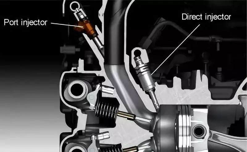
At low RPM and high load conditions, there are significant deficiencies in in-cylinder fuel injection. Specifically: the mixture of injected fuel and air is insufficient. This issue is more pronounced at lower intake flow rates (lower RPM).
Although this problem can be mitigated through in-cylinder rolling and swirling designs, the filling efficiency (VE) will decrease at high RPM. The instability of the mixture is mainly reflected in driving as torque instability.
To solve this issue, Toyota uses both manifold and in-cylinder injection methods on the 2GR-FSE and FA20 engines. Under low RPM and high load conditions, the majority of the fuel is injected by the manifold injector, with a smaller portion injected by the in-cylinder injector.
In the calibration of the 2GR-FSE engine, all fuel injection above 2600 RPM is done by the in-cylinder injector.
Water Injection System
To reduce cylinder temperature, suppress knock, improve VE, enhance power, and lower NOx and CO in exhaust gases, a water injection nozzle can be installed in the intake manifold.
The water injection system from Saab in 1978 allowed turbo pressure to increase from 0.7 bar to 1.2 bar.
The 2016 M4 GTS also uses a water injection system with a 5L water tank, 3 water nozzles, and water mist at 10 bar pressure.
This system can lower intake temperatures from 70°C to 45°C and increase turbo pressure from 1.3 bar to 1.5 bar.
More
-
Have you ever seen the combination of luxury cars and clear water concrete garages? -
How to build an E46 M3 that runs exclusively at the Nürburgring? -
I strive to play the role of an emotionally stable adult every day, but please allow me to collapse occasionally | AE86 x Mohe Dance Hall MV -
Besides Porsche and Subaru, Ferrari also has a V12 Flat engine
Today’s Signature