As a widely used communication bus between automotive ECUs, CAN has some fundamental questions related to its application, such as
-
Since it is a bus, why aren’t all connected together, and why are so many CAN interfaces needed?
-
Why do some associated transceivers require low power consumption while others do not?
1 Functions of Different CAN Ports
As a bus, CAN theoretically can connect all ECUs on a single line;
However, practical applications need to consider various influencing factors, such as communication real-time performance and success rate. To reduce the load rate on the CAN bus, the vehicle’s CAN is divided into categories like power CAN, calibration & diagnostic CAN, private CAN, etc.;
For example, the CAN network of traditional fuel vehicles or hybrid vehicles:
-
Power CAN: Used for basic communication, it connects nodes like the engine, transmission, ESP, etc. The baud rate is usually set to 500k, commonly referred to as power CAN.
-
Calibration & Diagnostic CAN: It reads internal variables of the engine through the calibration protocol CCP, with a baud rate typically set to 1M, usually called calibration CAN. This channel is generally disabled after mass production.
-
Private CAN: Present in hybrid vehicles, mainly adding many high-voltage components, such as battery packs, motors, DCDC, etc. Due to the high number of signals, a separate CAN channel is required.
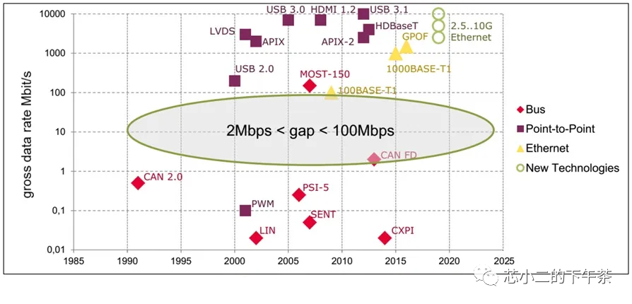
In pure electric vehicles, there are more ECUs, usually with one information CAN; as the overall vehicle data transmission volume increases and the amount of data per transmission grows, there is currently a basic need for CAN to support higher-speed CAN FD (not Fast CAN, but Flexible Datarate with variable rate and data field length).
2 CAN Bus Wake-Up
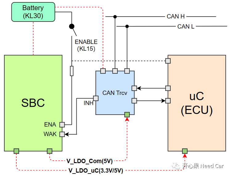
Some ECUs support sleep mode, and there are various ways to wake up the ECU, one of which is through a CAN message;
For example, in the BMS controller, after sleeping, when a specific message exists on the power CAN bus, the BMS’s CAN transceiver will output a wake-up signal INH, waking up the BMS control board to initiate the power-on process. This requires the CAN transceiver to support the bus wake-up function;
For CAN bus wake-up, you can refer to the article
How to Understand ECU Wake-Up, Sleep, and Reset?