The startup of the ECU definitely begins with the chip’s BootROM. I have previously written about the startup process of the Infineon Tricore series (if interested, click back to —>What Does Infineon TC27X Need to Do to Start). After the main chip kernel is initialized, what needs to be done for software initialization?
In today’s automotive ECU development, most have gradually adopted the AUTOSAR architecture. So how is the software power up and down process handled in the AUTOSAR architecture?
In the AUTOSAR architecture, the software power up and down process is mainly managed by the EcuM, which can be divided into two types:
1. Fixed EcuM: Used to manage the ECU’s fixed states, such as OFF, RUN, and SLEEP, as well as transitions between these states. This is sufficient for ECUs without special requirements (such as partial startup or fast startup). Additionally, Fixed EcuM does not support multi-core ECUs.
2. Flexible EcuM: Flexible EcuM has more powerful functions and higher flexibility, allowing for the following situations:
1. Partial or fast startup, where the ECU starts with a limited set of functions and then gradually starts up.
2. Interleaved startup, where the ECU starts minimally, then starts BSW and SWCs, thus interleaving the startup of BSW and applications.
3. Support for multi-core ECUs, where different states (startup, shutdown, sleep, wake-up) on all different cores of the ECU can be well coordinated.
The tasks managed by the EcuM module include:
1. EcuM is responsible for the initialization and de-initialization of BswM, SchM, and Autosar OS modules, as well as some basic software driver modules.
2. Responsible for handling different ECU states, including SLEEP and SHUTDOWN states.
3. EcuM also handles all wake-up events of the ECU, distinguishing between real wake-up events and unstable wake-up events.
In practical applications, most use Flexible EcuM, so the following will mainly introduce Flexible EcuM. As shown in Figure 1, it illustrates the state machine of Flexible EcuM.
Figure 1 Flexible EcuM State Machine
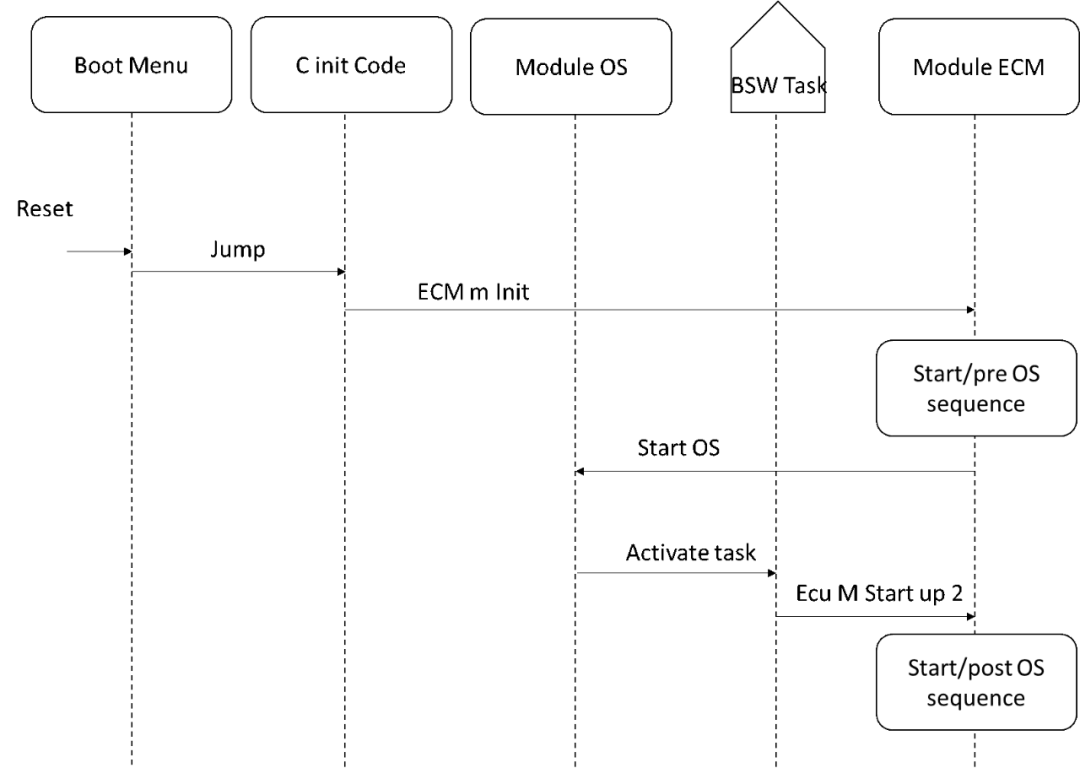
The STARTUP phase is divided into two parts, as shown in Figure 2. One part occurs before the OS starts, called StartPreOS. This part lays the foundation for initializing the OS, as shown in Figure 3. This phase should be as short as possible, with the main designed interfaces including:
1. EcuM_AL_DriverInitZero: Mainly used to initialize the DET module, allowing other modules to report any development errors, or it can remain an empty function.
2. EcuM_AL_DriverInitOne: Mainly used for initializing the peripherals of the main chip, such as GPIO, ADC, PWM, ICU, etc.
The second part of STARTUP is the StartPostOS sequence, which is activated after calling EcuM_StartupTwo. The following Figure 4 shows the order after PostOS startup in ECU initialization, mainly including:
Figure 4 StartPostOS Phase
1. Start the BSW Scheduler (SchM) – SchM stands for BSW Scheduler. It is used to load the configuration information of TASK in BSW.
2. Initialize the BSW scheduler – SchM_Init() is the function defined for initializing the SchM module. It is used to allocate and initialize the resources that the BSW Scheduler module will use. It can call OS services to trigger AUTOSAR OS tasks.
3. BswM_Init(), used to initialize the BswM module, ensuring that the rules and operation sequences configured in BswM can be triggered normally afterward.
After the EcuM starts the operating system and completes the initialization of SchM and BswM, the ECU enters the UP Phase. The UP Phase begins when the BSW Scheduler starts and calls BswM_Init. At this point, memory management, communication stack, and software components (SW-C) have not yet started. This phase is defined by the integrator, and the ECU transitions from one state to another, from one mode to another according to the integrator’s instructions.
The integrator must first be responsible for initializing NVM, then call NvM_Readall. Then trigger the rules configured in BswM to complete the initialization of the communication protocol stack, diagnostic protocol stack, network management, etc. After these initializations, start RTE, and then start SWC. This way, the program can run normally.
When the power down flag in the program is set, the SHUTDOWN phase begins. First, it will close the communication-related components and stop the periodic scheduling of RTE termination tasks, then shut down some modules such as DEM and BswM.Finally, call EcuM_GoDown(), which mainly completes the NvM writing and operates the SBC for power down.
In this phase, no code should be executed, but power is still provided to the ECU. This should be considered an energy-saving state to conserve energy. The ECU can respond to intentional or unintentional wake-up events. For unexpected wake-up events, the protocol provided by the EcuM module will ignore unexpected wake-up events. In a regular ECU, this state is usually not present.
When the ECU loses power, it enters the OFF state. In this state, it can be awakened by SBC.
The Electronic and Electrical Architecture of Tesla
The Pros and Cons of AUTOSAR
How to Achieve BootLoader Self-Update?
How to Implement CAN and CAN FD Networking Communication?
What Differences Will OTA and Remote Vehicle Diagnostics Bring?
Please Click “See” If You Appreciate the Effort