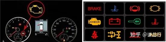
I have always been curious about what the warning lights on a car dashboard mean, when they appear, and when they disappear. Over the past two years, I have gained some knowledge in this area, and I would like to share it with interested friends.
This article will introduce the automotive controller (ECU) fault diagnosis system from three perspectives: system, design, and implementation:
-
From a system perspective, understand why a fault diagnosis system is needed, what it can do, and what it is;
-
From a design perspective, understand how faults are managed, identified, and handled;
-
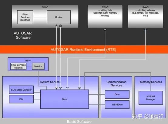
From an implementation perspective, understand the implementation mechanisms of the fault diagnosis system based on the AUTOSAR architecture.
1. Introduction to the ECU Fault Diagnosis System
Any part of a car or any interaction between parts can potentially fail. Even if the probability of failure is extremely low, we cannot guarantee that failure will not occur. Based on this fact, we cannot prevent failures, but we can identify potential failures as early as possible to minimize damage. Therefore, all automotive controllers need a fault diagnosis system to continuously monitor the system and components for abnormalities, identify faults, and once faults are identified, take temporary remedial measures to minimize damage while retaining fault information for subsequent troubleshooting and resolution. Thus, a complete ECU fault diagnosis system includes both an in-vehicle online diagnostic system and an off-vehicle offline diagnostic system. By using both together, a comprehensive fault diagnosis can be performed.
The in-vehicle online diagnostic system is used to monitor the working status of the vehicle’s sensors, electronic control units, and actuators, and based on this data, it automatically detects system faults, saves them in the form of fault codes, takes corresponding fault handling measures, and illuminates the corresponding warning lights to alert the driver.
The off-vehicle offline diagnostic system is used to extract saved fault information and can perform operations such as reading fault codes, clearing fault codes, and updating software by sending service requests (using UDS services) to the in-vehicle online diagnostic system, thus completing fault investigation and repair.
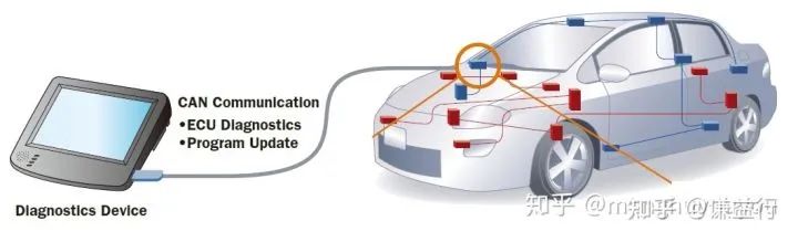
In other words, when a fault occurs in the vehicle, the in-vehicle online diagnostic system should activate, ultimately alerting the driver to the fault, prompting the driver to return the vehicle for repairs. The repair personnel will then need to use the off-vehicle offline diagnostic system to check fault information, find the cause, and perform software updates.
2. Key Points in the Design of the ECU Fault Diagnosis System
To implement the ECU fault diagnosis system mentioned above, and to lay the groundwork for the realization of the ECU fault diagnosis system, it is necessary to first introduce several important knowledge points in design, mainly including: Diagnostic Trouble Codes (DTC), fault diagnosis mechanisms, and UDS services.
2.1 Diagnostic Trouble Codes (DTC)
The ECU fault diagnosis system detects five main types of faults:
-
Mechanical/system faults, for example, faults related to the transmission controller, such as a faulty gear actuator or a malfunctioning clutch;
-
Electrical faults, such as short circuits in solenoids or sensors, or power supply voltages outside the operating range;
-
Hardware faults, mainly referring to device failures on the PCB, such as processor failures or peripheral chip failures;
-
Software faults, such as infinite loops, division by zero, overflows, etc.;
-
Communication faults, such as CAN connection failures or CAN message losses.
For these faults, diagnostic trouble codes (DTC) are used to represent them based on management and handling considerations. Let’s take a closer look at several important concepts related to DTC:
2.1.1 DTC Definition
DTC can be thought of as the