Various communication protocols are used in automotive ECUs. Previous articles introduced several serial communication methods, such as:
Understanding the SPI Protocol: Principles, Architecture, and Applications
Understanding the I2C Communication Protocol
Understanding the Differences Between I2C and SPI Buses
Chassis Domain Control: Have You Heard of AK and PSI5?
In this article, we will introduce another common serial communication method—UART communication.
Do you remember those bulky serial printers, mice, and modems on old desktop computers? The connectors were larger than fingers and had to be screwed in—yes, back then, most data was quietly transmitted via UART. Although USB has almost dominated all peripheral interfaces now, serial ports have not been eliminated; instead, they are thriving in embedded development scenarios.
When debugging on Arduino, STM32, or Raspberry Pi, whether you are working with a GPS module, Bluetooth module, serial display, or RFID reader, you will almost certainly encounter UART. It truly is the universal solution for embedded communication.
Today, let’s discuss: What exactly is UART, how does it work, what pitfalls should you be aware of, and what is it suitable for?
What is a Serial Port?
UART, short for Universal Asynchronous Receiver/Transmitter, is known in Chinese as “通用异步收发器” (Universal Asynchronous Transceiver), but we are more accustomed to calling it a serial port. Note that it is not a communication protocol like SPI or I2C, but a real circuit that may be integrated into an MCU or exist as a standalone chip.
Its primary function is simple:
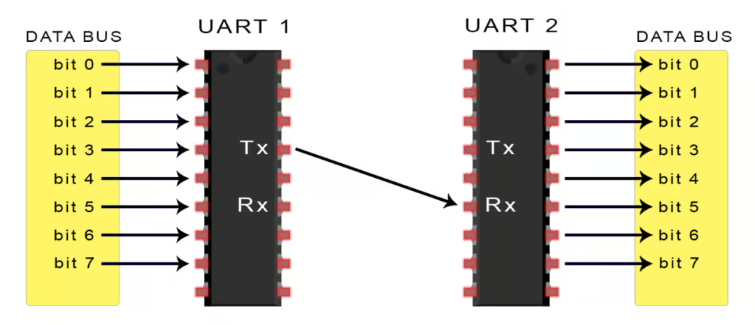
- To convert parallel data from the MCU into serial form for transmission;
- Or to convert received serial data back into parallel data for the system.
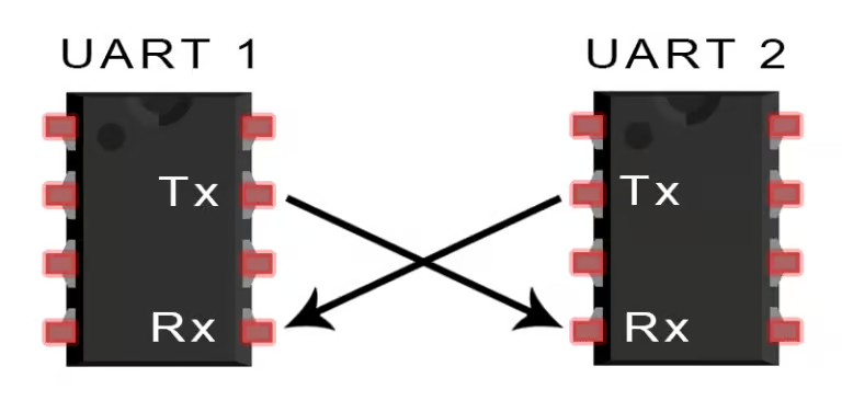
The best part: it only requires two wires—TX (transmit) and RX (receive)—to complete the communication, which is fewer than the multiple wires needed for SPI and I2C, making wiring much simpler.
How Does Serial Data Transmission Work?
UART communication is essentially two UARTs working against each other: one sends, and the other receives.
For example, if your development board needs to send data to a Bluetooth module:
- The internal data is parallel, and the UART transmitter will add some special markers (start bit, parity bit, stop bit), and then send it bit by bit;
- The receiving UART collects these bits, removes the framing, and restores the original data for output.
There is no clock synchronization signal; instead, it relies on a pre-agreed baud rate to maintain consistent timing. The baud rate indicates how many bits are transmitted per second, with common values like 9600bps and 115200bps.
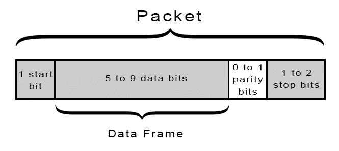
Typically, a data packet in the UART protocol looks like this:
- 1 start bit
- 5 to 9 data bits
- an optional 1 parity bit
- 1 to 2 stop bits
1. Start Bit
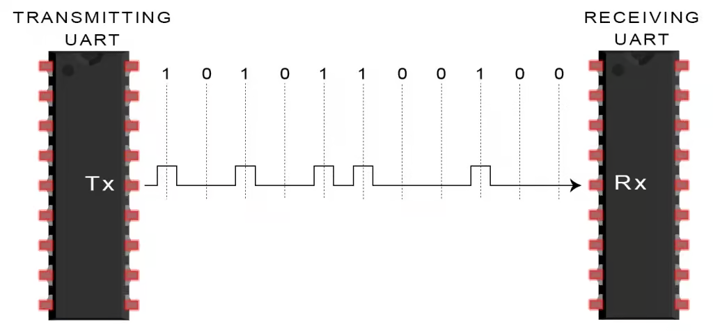
In the idle state, the TX pin is high (logic 1). When data is to be sent, it first pulls low for one bit (logic 0) to signal the receiver that it is “ready,” which is the start bit.
2. Data Bits
The actual data part is usually 8 bits, although some UARTs support 5 to 9 bits as options, with the most common being 8 bits without parity.
3. Parity Bit (Optional)
To detect errors during transmission, UART can include a parity bit. For example, “even parity” requires an even number of 1s, allowing the receiver to determine if there was an error based on the number of bits received. Note: This is not true error correction; it can only indicate an error, not “correct” it, and is much simpler than CRC or FEC.
4. Stop Bit
This indicates the end of the data packet. Typically, it is 1 or 2 bits of high logic level, giving the receiver a moment to breathe and preventing packets from merging.
The Complete UART Transmission Process
Here’s a five-step process for serial data transmission:
- The MCU sends the data to the UART (in parallel form)
- The UART packages the data into a frame, adding the start bit, parity bit, and stop bit
- The UART sends this packet bit by bit (through the TX pin)
- The receiving UART receives data from the RX pin
- The data is restored, removing the start bit, parity bit, and stop bit, and sent back to the system
UART Debugging Matters
When it comes to serial communication, we must mention debugging. In actual projects, UART is not only used for data communication but also serves as an important window for us to communicate with the MCU.
Common Debugging Methods
-
USB to Serial Modules such as CH340, CP2102, FT232, etc., are standard debugging tools for UART.
- Advantages: They are inexpensive, easy to wire, and when used with serial assistant software, you can see every log sent by the MCU.
Serial Assistant Tools commonly used in China include SSCOM, XCOM, SecureCRT, and MobaxTerm.
- For a more professional approach, you can use a logic analyzer to capture waveforms and check if the start and stop bits are correct.
Serial Print Log Techniques The most common debugging method for embedded programs is to use printf to print debug information.
- Note: Serial ports are IO resources and can affect interrupt response times, so do not use printf in interrupts.
- Suggestion: If necessary, use a circular buffer for asynchronous printing to reduce blocking.
Can UART Achieve Multi-Device Communication?
Although UART is point-to-point communication, it is still possible to have a host control multiple slave devices. Here are a few solutions:
- Multiple UART peripherals on STM32: such as USART1, USART2, etc., which can correspond to multiple devices.
- DMA + Multiplexing: Some chips support DMA with multiplexing for efficient multi-device communication.
- Software UART: Simulating a serial port using timers and GPIO (bit-banging), suitable for low baud rate scenarios.
Reminder: Once multiple UARTs are in use, remember to plan the baud rates and interrupt priorities to avoid data loss.
Some Tips & Pitfalls
1. Baud Rate Mismatch Issues
Once while debugging a GPS module, I found that the data was always garbled, and it turned out that the module’s default was 9600bps, while I was using 115200.Note: Serial communication relies on both sides agreeing on the baud rate!
2. Serial Print Lag
Using printf on STM32 is blocking by default, and prolonged serial output may freeze the main program.Solution: Use non-blocking output or DMA for optimization.
3. Serial Debugging Garbled Output
Be aware of encoding issues, especially when using Chinese serial assistant software on Windows.Note: It is recommended to use UTF-8 encoding consistently.
In Conclusion
UART is essentially the simplest, most stable, and hassle-free communication method. From the earliest computer communication interfaces to today’s core communication method in embedded devices, UART remains an indispensable part of our development toolbox.