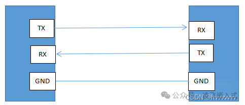
The UART (Universal Asynchronous Receiver/Transmitter) is a serial communication device that serves as a bidirectional, serial, asynchronous communication bus. It can achieve full-duplex communication using one data receiving line (RX), one data transmitting line (TX), and a ground line (GND). As shown in the figure below:
When communicating using UART, the unit of transmission is the data frame. A complete data frame includesdata bits, astart bit, aparity bit, andstop bits, where the parity bit can be optionally added based on requirements, and the number of stop bits can be configured. The UART frame format is shown in the figure below.
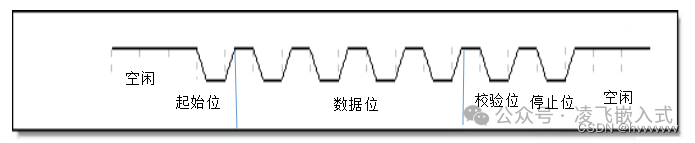
Note: UART is in an idle state when there is no data transmission, with both TX and RX lines at a high level. When TX needs to transmit data, it first sends a start bit (low level). When RX detects the start bit (low level), it begins data reception. UART can use theparity bit to determine whether the data transmission is correct. UART usesstop bits to determine whether a data byte (1 byte) has been completely transmitted. Only after receiving the stop bit can the next data transmission begin.Start Bit: When transmitting data using UART, there is no unified clock between the sender and receiver. If the sender sends data directly, the receiver will not know when data is being transmitted, which may lead to data errors during reception. Therefore, aflag bit is needed to indicate the start of data transmission. TX and RX are in an idle state when there is no data transmission, and the bus is athigh level. Thus, when a low level appears on the RX line during idle state, it indicates the start of data transmission. The RX line detects a low level after the stop bit or during idle state, indicating that data transmission is occurring.Data Bits: The data bits are the actual data to be transmitted. The number of data bits can be programmed based on communication requirements, typically set between 5 to 8 bits, with 8 bits being the standard. Before data transmission, both the sender and receiver need to agree on the number of data bits to avoid data loss or duplication.Parity Bit: When using UART for data transmission, a parity bit can be added to the data frame to check the correctness of the data transmission. UART uses odd or even parity, typically placed before the stop bit. If a parity error occurs, it indicates that an error occurred during data transmission, and the received data is invalid. If the odd/even parity check is correct, the data can be received and further transmitted. Configuration work is required before data transmission between the sender and receiver to choose whether to add a parity bit to the data frame.Stop Bit: The stop bit is at the end of a data frame. By default, the stop bit is 1 bit of high level, but it can also be configured to 1.5 or 2 bits based on usage requirements. If the stop bit is not received at the expected position, it will result in aframe error.Idle: The UART bus is in an idle state when there is no data transmission.In idle state, the RX and TX ports of UART are at high level.Baud Rate: Since UART communication is asynchronous, there is no synchronized clock line between the sender and receiver. To ensure correct data transmission, the sender and receiver must define the same transmission rate. The communication rate of UART serial ports is expressed in baud rate; the higher the baud rate, the faster the transmission rate. UART typically generates the corresponding baud rate clock by counting and dividing the system clock, and the receiver and transmitter use this clock for data sending and receiving. To avoid interference from signal glitches during data reception, sampling is generally performed at the midpoint of the data. The receiver starts receiving data when it detects a falling edge on the RX line. If it only relies on detecting the falling edge to consider the start bit valid, glitches or invalid start bits on the line may lead to receiving invalid data, resulting in transmission errors. After detecting the falling edge, sampling is performed at the midpoint of the start bit to ensure that the start bit is valid; otherwise, the start bit will be discarded, and monitoring for a valid start bit will continue.