Introduction to the SPI Protocol
SPI is the Serial Peripheral Interface. It is a synchronous serial interface technology introduced by Motorola, characterized by high speed and full-duplex synchronous communication, capable of operating at frequencies exceeding hundreds of MHz. Typically, SPI requires four lines (for duplex communication), but it can also operate with three lines (for simplex communication). It is widely used in devices such as ADCs, LCDs, and memory, making it suitable for applications that demand high communication speeds.
Features of the SPI Interface
1. The SCK clock signal line is controlled solely by the master device; the slave device cannot control the clock signal line. In an SPI communication, there is at least one master device.2. Unlike ordinary serial communication, which transmits at least 8 bits of data continuously (such as UART, which includes start bits, stop bits, and optional parity bits), SPI allows data to be transmitted one bit at a time and even permits pauses. Since the SCK clock line is controlled by the master device, when there are no clock transitions, the slave device does not collect or transmit data. This means that the master device can control the communication through the SCK clock line.3. SPI is full-duplex communication; because the data input and output lines are independent, it allows simultaneous data input and output. Different implementations of SPI devices may vary, primarily in the timing of data changes and sampling, with different definitions for sampling on the rising or falling edge of the clock signal. Under the control of the SCK clock line, two bidirectional shift registers exchange data.4. In point-to-point communication, the SPI interface does not require addressing operations and is simple and efficient due to its full-duplex nature. In systems with multiple slave devices, each slave requires an independent enable signal, making the hardware slightly more complex than I2C systems. A drawback of SPI is the lack of specified flow control and no acknowledgment mechanism to confirm data reception.
Hardware Layer of SPI
SPI is a communication method that adopts a master-slave mode, supporting one master to one slave and one master to multiple slaves, but not multi-master mode. A common connection method for one master to multiple slaves is as follows:
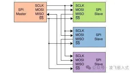
CS/SS: Slave Chip Select Enable Signal Line. This signal is controlled by the master. In a one-master to multiple-slave mode, each slave requires a CS/SS line for the master to select which slave to communicate with (generally active low). When multiple SPI slave devices are connected to the SPI master, the other signal lines SCK, MOSI, and MISO can be connected in parallel to the same SPI bus, meaning that regardless of the number of slave devices, these three lines can be shared; each slave device has its own independent CS/SS signal line, so the number of CS/SS lines equals the number of slave devices. Unlike the I2C protocol, which uses device addresses for addressing, SPI does not have device addresses but uses chip select signal lines for addressing. When the master wants to select a slave device, it typically sets the chip select signal line of that device to low, thus selecting it and establishing communication between the master and the slave.SCK: Clock Signal Line. Generated and controlled by the master. Used for synchronizing communication data, but the communication speed supported by different devices may vary, and it is important to note that the communication speed is limited by the slower device.MOSI/SDO: Master Output/Slave Input Pin, this data line is used only for sending data from the master to the slave.MISO/SDI: Master Input/Slave Output Pin, this data line is used only for sending data from the slave to the master.
SPI Communication Protocol
The SPI protocol defines the start signal, stop signal, data validity, clock synchronization, etc. Its communication timing is as follows:
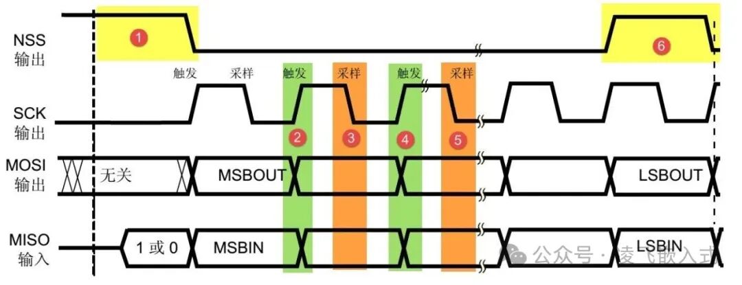
Start Signal: The CS/SS signal transitions from high to low, indicating the start of SPI communication; the timing diagram’s ① represents the start signal, controlled by the master, which changes CS/SS from high to low to select the slave for communication, followed by the master generating the clock signal SCK to initiate data transmission.Stop Signal: The CS/SS signal transitions from low to high, indicating the stop signal for SPI communication; the timing diagram’s ⑥ represents the stop signal, controlled by the master, which changes CS/SS from low to high to end the data transmission.Data Validity: SPI uses the MOSI and MISO signal lines to transmit data, as shown in the timing diagram’s ②③④⑤, indicating that the data on MOSI and MISO changes output (triggered) during the rising edge of SCK and is sampled (captured) during the falling edge of SCK. This means that at the moment of the falling edge of SCK, the data on MOSI and MISO is valid, with high level representing data ‘1’ and low level representing data ‘0’. At other times, the data is invalid.Clock Synchronization: Data transmission in SPI requires the use of the SCK signal line for data synchronization. The MOSI and MISO data lines transmit one bit of data during each clock cycle of SCK, completing data preparation and sampling within that cycle, and data input and output occur simultaneously. In SPI, data can be either MSB first or LSB first; there are no strict regulations in the protocol, as long as both communicating parties maintain consistency.