1. Reset
(1) What is Microcontroller Reset
The reset of the STM32 microcontroller refers to the process of resetting the microcontroller to its initial startup state. The reset behavior causes all running programs to terminate and restores the microcontroller’s registers and functions to their initial values. The reset process provides a known starting state for the program, allowing it to safely start or restart code execution.
The STM32F10xxx supports three types of reset: system reset, power-on reset, and backup domain reset.
System Reset:
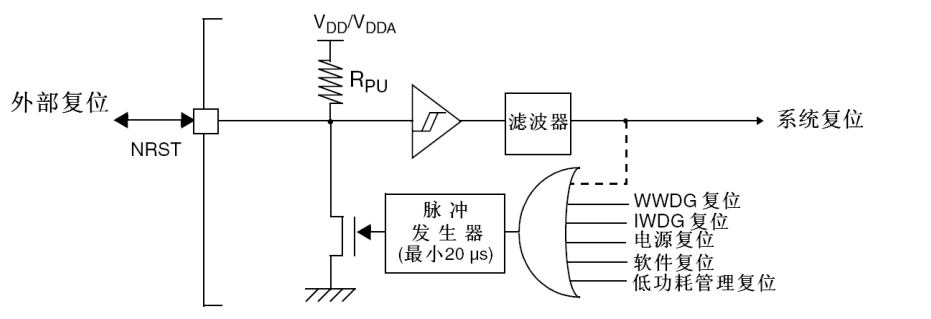
A system reset is generated when any of the following events occur: (The source of the reset event can be identified by checking the reset status flags in the RCC_CSR control status register.)
1. Low level on the NRST pin (external reset)
2. Window watchdog timeout (WWDG reset)
3. Independent watchdog timeout (IWDG reset)
4. Software reset (SW reset)
A software reset can be achieved by setting the SYSRESETREQ bit to ‘1’ in the Cortex™-M3 interrupt application and reset control register.
5. Low-power management reset
A low-power management reset is generated when entering standby mode: enabling this reset can be done by setting the nRST_STDBY bit in the user option byte to ‘1’. At this point, even if the process to enter standby mode is executed, the system will be reset instead of entering standby mode.
A low-power management reset is generated when entering stop mode: enabling this reset can be done by setting the nRST_STOP bit in the user option byte to ‘1’. At this point, even if the process to enter stop mode is executed, the system will be reset instead of entering stop mode.
Power-on Reset: A power-on reset is generated when any of the following events occur:
1. Power-on/reset (POR/PDR reset)
2. Returning from standby mode
Backup Domain Reset: The backup domain has two dedicated resets that only affect the backup domain. A backup domain reset is generated when any of the following events occur:
1. Software reset, which can be triggered by setting the BDRST bit in the backup domain control register (RCC_BDCR) (see section 6.3.9).
2. Powering on VDD or VBAT with both VDD and VBAT powered down will trigger a backup domain reset.
Reset Circuit:
What Happens After Successful Reset of the Microcontroller:
All I/O pins will be configured to their default state (most are floating inputs).
Most registers will be set to their default reset values.
The microcontroller stops executing the current program and restarts.
The microcontroller begins executing code from its preset startup address, usually the entry point of the bootloader or main program.
Reset is a key feature for the reliability and stability of microcontrollers, ensuring that even after severe errors or exceptions, the device can return to a known and safe operating state. In application development for microcontrollers like the STM32, understanding and correctly implementing the reset mechanism is crucial for creating robust systems.
(2) External Reset Circuit Design
Having discussed reset extensively (I can hardly recognize the term now), the most commonly used are power-on/reset and external reset, where the external reset is entirely determined by the level on the NRST pin. When the level on the NRST pin is less than 0.8V, and the input pulse time is 100ns, the microcontroller undergoes an external reset.
Now, please see the circuit diagram:
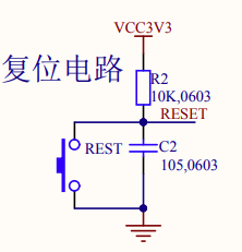
Although I’ve covered quite a bit, at least the circuit diagram is still quite simple, right?
First, look at resistor R2, which acts as a pull-up resistor to pull the NRST pin high (marked as RESET in the diagram).
# Pull-up Resistor ensures a high level (logic high) state at a node in the circuit when there are no other inputs by connecting to the positive supply voltage (usually Vcc).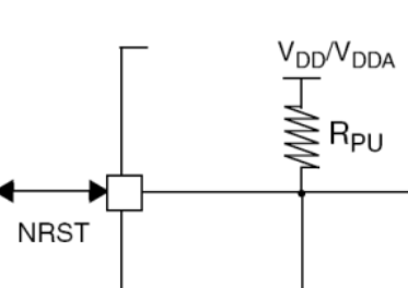
In simple terms, this is because the internal pull-up may not be sufficient to ensure the system’s reliability under all operating conditions. Therefore, even if the NRST pin already has an internal pull-up resistor, it is still recommended to pull up the NRST pin externally.
Why is a 10k resistor value chosen?
The reason for choosing 10kΩ as the pull-up resistor is that it provides a reasonable compromise. We need to consider various factors such as power consumption, input voltage pull-up capability, and current when the button is pressed. A larger resistor value can reduce static power consumption. When the button is not pressed, the current flows through the pull-up resistor to the NRST pin of the microcontroller. If the resistor value is too small, this current will increase, consuming more power. When the button is pressed, a current loop is formed between the pull-up resistor and the NRST pin of the microcontroller. The smaller the resistor, the larger the current flowing through the button. This current should not be too large, as it may cause unnecessary power consumption and possible damage. However, the resistor also needs to be small enough to ensure that even with the maximum allowable input leakage current, the voltage on the NRST pin can be pulled up to a level recognized as high. Hence, 10k is just right.
Next, let’s look at capacitor C2 and the button. The button serves to ground the NRST pin, but there is button bounce when the button is pressed, and the capacitor can debounce in this scenario.
# Button Bouncing refers to the rapid fluctuations in the electrical signal caused by imperfect contact points during the operation of mechanical switches or buttons.The capacitor model is 105, so the capacitance is 1 microfarad. Why choose a 105 capacitor instead of a larger or smaller one?
The goal when selecting a capacitor is to find an appropriate value that allows the capacitor to effectively debounce when the button is pressed and quickly provide a stable high-level signal to the microcontroller’s reset pin when released. 1μF is an optimal choice because:
For larger capacitance values:
Extended debounce time: A larger capacitor will increase the debounce time of the circuit, causing a delay in the reset signal, increasing the delay between button press and reset action.
Increased power surge: When the button is released, a larger capacitor will take more time to charge, leading to larger current spikes on the power line, affecting power stability or other parts of the circuit.
Physical size: Larger capacitors may also have larger physical sizes, which may not be suitable for compact circuit board designs.
For smaller capacitance values:
Insufficient debounce: If the capacitor is too small, it may not provide enough debounce effect, leading to unstable contacts or multiple reset triggers in a short time.
Faster response time: Although smaller capacitance can reduce debounce time and provide faster response, if too small, it may not filter out voltage fluctuations caused by poor mechanical contact.
The choice of 1μF capacitor is based on the consideration that it provides sufficient debounce effect while not excessively prolonging the response time of the reset signal. This value also takes into account the charging and discharging times of the capacitor, ensuring that after the button is released, the NRST pin can quickly return to a high-level state.
We can also simulate mentally:
The moment the button is pressed, the voltage on the NRST pin should still be VCC, as C2 is connected between NRST and ground (the voltage across the capacitor does not change instantaneously). The voltage will decrease as C2 discharges, but since the capacitor is in parallel with the button, this effectively shorts the capacitor, even though the time for button bounce is generally very short (usually 5-10ms for micro-switch button bounce), so the low level lasts for 100ns before the microcontroller resets. After 100ns, the button is still bouncing, and when the bounce causes the button to disconnect, VCC charges the capacitor through the 10k resistor. We can calculate how long it takes for the capacitor to charge to 0.8V:
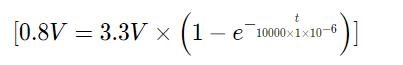
To calculate the time required for the capacitor to charge to a specific voltage, we can use the charging equation for an RC circuit:
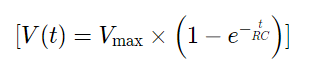
Where: (V(t)) is the voltage at time (t). (Vmax) is the supply voltage, which is 3.3V here. (R) is the resistor value, which is 10kΩ (10000Ω) here. (C) is the capacitor value, with 105 indicating the capacitance is 10×10^5 pF, or 1μF (1×10^-6 F). (e) is the base of the natural logarithm, approximately equal to 2.71828. (t) is time in seconds.
We want to solve for the time (t) required for the capacitor to charge to 0.8V.
First, we substitute all known values into the equation:
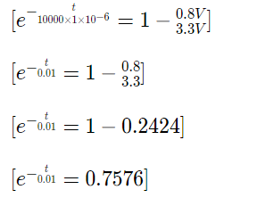
To solve for (t), we first isolate (e) in the equation:
Now, taking the natural logarithm to solve for (t):
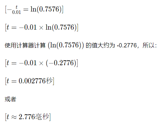
After some calculations, we find that it takes approximately 2.776 milliseconds to charge to 0.8V. Of course, this is a theoretical calculation; in practical circuits, factors such as resistor and capacitor tolerances, voltage fluctuations, etc., may affect this time. Thus, we can infer that a 105 capacitor is sufficient to keep the voltage below 0.8V during button bouncing, preventing the microcontroller from repeatedly resetting.
When the button is released, it can also stabilize the pull-up voltage without jumping around.
All theoretical calculations need to be grounded in practice; the most suitable capacitor value still depends on the specific application scenario and circuit design. In actual circuit design, we need to determine the optimal capacitor value through experimentation and adjustments. For instance, if the mechanical characteristics of the reset button differ (such as different switch bounce characteristics), we need to adjust the capacitor value to optimize performance.