 Search WeChat
 Skill Training
The NPN transistor consists of three pieces of semiconductor material, two of which are N-type and one is P-type. The P-type semiconductor is in the middle, with the two N-type semiconductors on the sides. The transistor is one of the most important components in electronic circuits, primarily functioning as a current amplifier and switch.
Working Principle

In fact, as long as you understand the characteristics of the transistor, it will be much easier for you to use microcontrollers. Everyone knows that transistors have amplification functions, but truly understanding them is key to using most electronic circuits and ICs in the future.
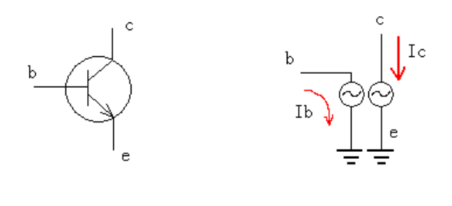
The ordinary transistor we refer to typically has current amplification properties. Other types of transistors extend functionality based on this principle. The symbol for a transistor is shown in the left diagram; we will take the NPN transistor as an example to discuss its working principle.
“
It acts as a device that uses the base current Ib to drive the collector-emitter current Ic, functioning similarly to a controllable valve.
”
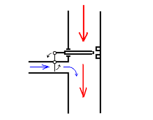
The blue small water flow in the left thin tube pushes the lever to open the valve of the large water pipe, allowing a larger red water flow to pass through this valve. The larger the blue water flow, the greater the red water flow in the large pipe.
If the amplification factor is 100, then when the blue small water flow is 1 kg/hour, it allows the large pipe to flow 100 kg/hour of water.
The principle of the transistor is similar; with an amplification factor of 100, when the base current Ib is 1 mA, it allows 100 mA of current to pass through Ice.
You may know this principle, but understanding how it applies in circuits will eliminate a significant barrier to using microcontrollers.
The most common connection is shown in the diagram below:
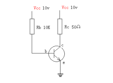
Let’s analyze this circuit. If its amplification factor is 100 and we ignore the base voltage, the base current is 10V ÷ 10K = 1 mA, and the collector current should be 100 mA.
According to Ohm’s Law, the voltage across Rc would be 0.1A × 50Ω = 5V. Thus, the remaining 5V is dropped across the transistor’s collector and emitter.
Good!
Now, if we set Rb to 1K, then the base current is 10V ÷ 1K = 10 mA. If we calculate Ic based on the amplification factor of 100, it would be 1000 mA, or 1 A. If it really were 1 amp, then the voltage across Rc would be 1A × 50Ω = 50V.
Huh? 50V! That exceeds the power supply voltage. Has the transistor become a generator? It’s not like that.
See the diagram below:
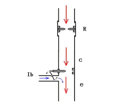
We will still use the flowing water analogy for current. When the control current is 10mA, it allows the main water pipe’s valve to open wide enough to flow 1A of current. However, that doesn’t mean there will be 1A of current flowing.
No, because there is still a resistor upstream, which acts like a valve with a fixed opening. It is placed in series with this main water pipe. When the controllable valve opens wider than the fixed resistor’s opening, the water flow will no longer increase but will equal the flow through the fixed valve opening. Therefore,
the transistor below cannot increase its opening any further.
Thus, we can calculate that the maximum current through the fixed resistor is 10V ÷ 50Ω = 0.2A, or 200mA.
This means that in the circuit, as the base current increases, the collector current also increases. When the base current Ib increases to 2mA, the collector current increases to 200mA. When the base current increases further, the collector current will no longer increase and will remain at 200mA.
At this point, the upper resistor is limiting the current.
Next, let’s understand the state of the IO in the microcontroller:
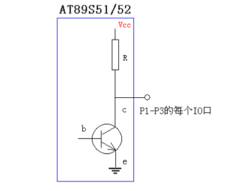
The circuits of the 24 IO ports P1-P3 in the microcontroller are all like the diagram above.
The purpose of using electronic circuits is ultimately to make target devices work, such as turning on LEDs or making motors run. Essentially, this means providing these devices with sufficient current to do work. For example, to light an LED, a current of more than 1mA is generally required.
However, microcontrollers are intelligent chips that can perform logical analysis and judgment by detecting the voltage values of each IO port and can output high or low voltage as result signals. Therefore, it can be seen that the IO ports of microcontrollers focus on the voltage produced rather than the current flowing through R and the transistor.
So what is the relationship between the voltage and current at the IO ports of the microcontroller?
We will again use the flowing water analogy:
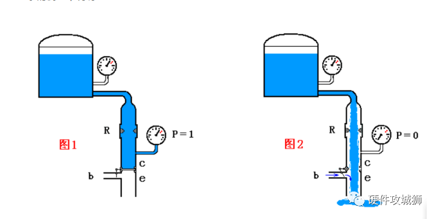
Assuming we open the valve R wider and close the control valve below, as shown in Figure 1, we can see that the pressure at point P is the pressure of the water tank.When we fully open the control valve below, as shown in Figure 2, water will flow through the pipeline with a large flow, and at this time the pressure at point P becomes 0.This principle is very similar to electronic circuits.
By opening or widening the transistor, the logical quantity measured at the output point P can be 1 (power supply voltage) or 0 (0 potential).
However, there is a problem with this process: when the output at point P needs to be 0, the transistor will open wide, and the current flowing through will be large. With 32 IO ports on the microcontroller, this will consume a lot of energy.
Is there a way to improve this?Yes!See the diagram below:
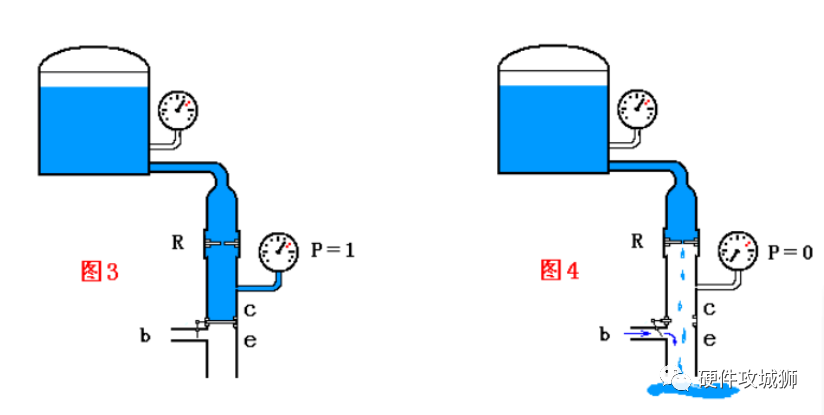
See Figure 3. If we reduce the upper valve R significantly and close the control valve below, the pressure at point P will still be the pressure of the water tank, just like in Figure 1. However, when we open the control valve, the pressure at point P will also be 0, but the water flow will be greatly reduced.This way, we can output 1 or 0, but consume very little water.
The circuit in the microcontroller does exactly this; the resistor R above is about 50K, and the maximum current is 5V ÷ 50K = 0.1mA.
In other words, when P outputs 1, it consumes no current; when P outputs 0, the current consumed is 0.1mA.Because of its large pull-up resistor R, it requires certain techniques to directly drive an LED or other loads.
Now let’s analyze various situations when the IO port is connected to external loads:

First, let’s look at the situation when connecting to TTL devices. When P1.0 is connected to an input pin of 74HC373, the input impedance of TTL devices is very high, around hundreds of K to M ohms.
This is equivalent to connecting a 500K (assuming 500K) resistor from P1.0 to ground. Thus, when the transistor is on, P1.0 is at a low level, and a current of 0.1mA flows through Rc and then through the transistor to ground, with no current flowing through Ri.When the transistor is off, the current flows from Rc through Ri to ground.Due to the voltage division effect, there will be some voltage across Rc and Ri, and the voltage at point P1.0 will be the voltage division of Rc and Ri.
Total current = 5V ÷ (50K + 500K) = 0.009mA, thus P1.0 voltage = 0.009mA × 500K = 4.5V.
TTL specifies that output of 2.4-5V is high level; output of 0.4-0 is low level. Thus, this connection is correct.
Next, let’s look at the situation of driving an LED with S51:
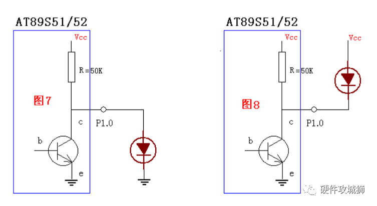
Let’s first look at the situation in Figure 7. Clearly, the LED’s direction is positive up and negative down, and only when P1.0 is at a high potential can the LED light up. To make P1.0 high, the transistor must be off.When the transistor is off, the current flows from Rc to the LED and then from the LED to ground.For the LED to conduct, there must be a threshold voltage of more than 2.1V across the LED.Thus, the current through the LED = (5V – 2.1V) ÷ 50K = 0.058mA. Can you say the LED will light up?Now let’s look at Figure 8. From the diagram, it can be seen that to turn on the LED, P1.0 must be at a low potential. The transistor at P1.0 must conduct. Once the transistor conducts, the current flows from Rc through the transistor to ground. Another path consumes 2.1V across the LED. The current flows through the transistor with almost no resistance, and the maximum current of the IO port transistor cannot exceed 15mA; otherwise, it will burn out the transistor. Therefore, this connection is incorrect.So how can both methods drive the LED?See the diagram below: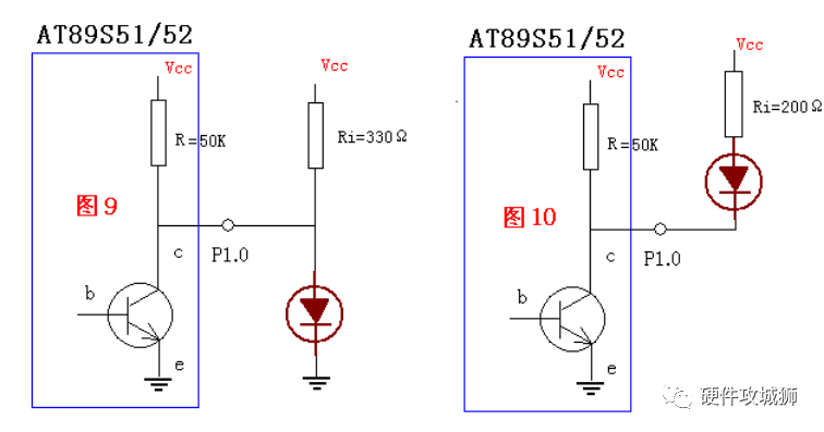 First, look at Figure 9. Connect a resistor Ri between P1.0 and Vcc. When the transistor conducts, two currents must flow through its CE. One is the internal current of 0.1mA, and the other is the current through Ri. To prevent the transistor from overcurrent and burning out, we need to determine its resistance value.Ri = 5V ÷ 15mA = 0.333K, which is about 330 ohms. The current through the transistor will be approximately 15mA, and at this point, the LED will not light up.When the transistor is off, both currents must flow through the LED. What will the current through the LED be? The current flowing through the internal resistance of S51 is (5V – 2.1V) ÷ 50K = 0.06mA, which is negligible. The current through Ri will be (5V – 2.1V) ÷ 330Ω = 0.0087A, or 8.7mA. This is enough to make the LED relatively bright.This driving method is feasible, but notice that the current consumed when the LED is off is greater than when the LED is lit.If multiple IO ports are used to light many LEDs, this circuit would not be economical.Good! This is the situation of directly driving the LED with a high level at P1.0.Now let’s look at Figure 10, where a resistor is connected in series with the LED between Vcc and P1.0. When the transistor conducts, two currents must flow through the transistor’s CE. The internal current remains 0.1mA, and the current through the LED must be determined to ensure the transistor’s CE does not exceed 15mA. Thus, the resistor value is (5V – 2.1V) ÷ 15mA = 0.193K, approximately 200 ohms. This way, the current through the LED is about 15mA, making it quite bright. When the transistor is off, it blocks the paths of these two currents, thereby consuming no current. This circuit is the situation of directly driving the LED with a low level at P1.0, where the LED consumes 15mA when lit and no current when off, making this circuit the most suitable. The S51 directly driving the seven-segment display generally uses this circuit principle.Below is the schematic of the seven-segment display: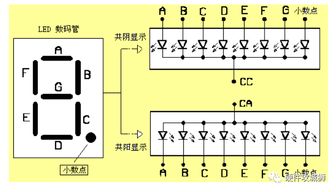
— End —
This account maintains neutrality regarding all original and reprinted articles’ statements and views. The articles and images’ copyrights belong to the original authors. If there is any infringement, please contact us for deletion.
HISTORY/Past Recommendations
Complete question bank for the 2023 Electrician Level 1 Exam (includes answers)
Three essential tools for electricians, easily accessible via WeChat!
[Collection] The “Path” of a veteran electrician with a monthly income exceeding 10,000!
Which of the five major electrical drawing software (CAD, Eplan, CADe_simu…) do you prefer?
Latest electrical version of CAD drawing software, with a super detailed installation tutorial!
Latest electrical drawing software EPLAN, with a super detailed installation tutorial!
Common issues for beginners using S7-200 SMART programming software (includes download links)
Comprehensive electrical calculation EXCEL sheets, automatically generated! No more asking for help with electrical calculations!
Want Bluetooth headphones or beginner books on electricians/PLC? Come and claim your electrical gift!
Basic skills of PLC programming: Ladder diagrams and control circuits (includes 1164 practical cases of Mitsubishi PLC)
Still can’t understand electrical diagrams? Take away the basics of electrician diagram recognition and simulation software to quickly get started with theory and practice!
12 free electrician video courses, 10GB software/e-book materials, and 30 days of free electrician live classes are being given away!
Don’t forget to like + check it out!
 Click “Read the original text” to learn PLC/electrician courses for free!