1. Repair Procedure for Burnt IGBT or Fuse on Circuit Board
If the current fuse or IGBT is burnt, you cannot immediately replace the component. You must confirm that the following other components are in normal condition before proceeding with the replacement; otherwise, the IGBT and fuse will burn out again.
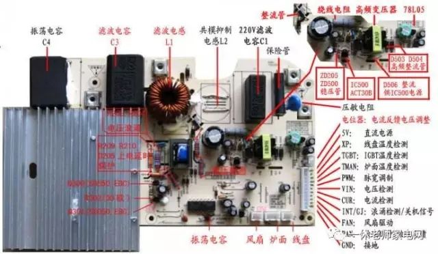
1. Visually check if the current fuse is blown.
2. Test if the IGBT is shorted:
Use a multimeter in diode mode to measure the IGBT’s “E”, “C”, and “G” terminals for breakdown.
A: There should be no conduction in both directions between “E” and “G”; “C” and “G” (normal).
B: When the red probe of the multimeter connects to the “E” terminal and the black probe to the “C” terminal, there should be a voltage drop of about 0.4V (for the model GT40T101, it should be fully non-conductive).
3. Measure if the transformer has broken legs; the normal state is as follows:
Use the multimeter in resistance mode to measure the secondary resistance of the transformer, approximately 80Ω; primary should be 0Ω.
4. Check if the rectifier bridge is functioning normally (test with the multimeter in diode mode):
A: Connect the red probe to “-” and the black probe to “+” to see a voltage drop of about 0.9V; reverse connection shows no display.
B: Connect the red probe to “-” and the black probe to both input terminals, each should show a voltage drop of about 0.5V; reverse connection shows no display.
C: Connect the black probe to “+” and the red probe to both input terminals, each should show a voltage drop of about 0.5V; reverse connection shows no display.
5. Check capacitor C301, C302, C303 for heat damage. (If damaged, they may be deformed or melted)
6. Test if chip 8316 is shorted:
Measurement method: Use the multimeter to measure the pins of 8316, pins 1 and 2; 1 and 4; 7 and 2; 7 and 4 should not be shorted.
7. Check if the thermal switch insulation protection at the IGBT is damaged. For poor button action detection, measure if the CPU pin lines are shorted:
2. Poor Button Action
Use the multimeter in diode mode to measure the CPU pin and ground; there should be a voltage drop of about 0.7V, with the red probe on “ground” and the black probe on “each CPU pin line”. Otherwise, it indicates a short in the CPU pin line.
3. Power Not Meeting Requirements
1. Coil short circuit: Test the inductance of the coil; PSD coefficient is L=157±5?H, PD series is L=140±5?H.
2. Check if the distance between the cookware and the coil is normal.
3. Check if the cookware is the specified type.
4. Check if all components are loose or missing
Inspection of assembly issues:
1. No heating: Check if the transformer has broken legs.
2. Continuous beeping after plugging in: Check if the temperature switch terminals are properly connected.
3. Unable to power on: Check if the thermal resistor terminals are properly connected.
4. No small object detection (no alarm): Check if resistors R301~R307 are normal.
R301~R302 is 68KΩ
R303~R306 is 130KΩ
R307 is 3.0KΩ
5. Fan not spinning; check if transistor Q2 is burnt out. (Typically, burnt transistor leads will appear yellow; can also be tested with a multimeter in diode mode)
Welcome to contribute to discuss the development of the home appliance service industry!
Likes are a form of encouragement, share to spread friendship!情