A comprehensive analysis of the CAN bus physical layer based on ISO11898 and ISO11519
1 CAN Hardware Control Layer
CAN communication[1] is an asynchronous communication method, differing from synchronous communication methods like I2C and SPI that rely on clock signals. CAN communicates through a pair of differential signal lines, <span>CAN_H</span> and <span>CAN_L</span>, using differential signals for communication.
The physical layer of the CAN bus, along with the data link layer, constitutes the hardware control of the CAN protocol (ISO11898/ISO11519).
- • The physical layer specifies the media, electrical signal specifications, and other parameters such as cables and connectors used during communication to facilitate signal transmission between devices. For example: signal levels, transceivers, cable types, and connector forms.
- • The data link layer takes the signals (bit sequences) received from the physical layer and organizes them into meaningful data, providing error control and other data transmission control processes.
1.1 Comparison of <span>ISO11898</span> and <span>ISO11519</span>
Communication Speed/Distance
Both protocols define the communication standards for CAN, but there are subtle differences:
- •
<span>ISO11898</span>primarily targets high-speed CAN buses with communication speeds ranging from<span>125kbps-1Mbps</span>and bus lengths of<span>< 40m</span>. - •
<span>ISO11519</span>is mainly aimed at low-speed CAN communication with speeds below<span>40kbps-125kbps</span>and bus lengths of<span>< 1km</span>.
Bus Network Form
Both standards utilize twisted pair cables for transmission, maintaining an impedance of 120 ohms (85~130 ohms), with bus delay times kept at 5ns/m. For high-speed, short-distance CAN networks adhering to the <span>ISO11898</span> standard, each end of the bus requires a “120 ohm” termination resistor, forming a closed-loop bus network:
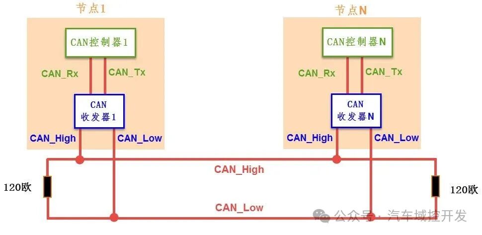
Image from doc.embedfire.com
For low-speed, long-distance CAN networks adhering to the <span>ISO11519</span> standard, the two bus lines are independent and do not form a closed loop, requiring a <span>2.2k ohm</span> resistor in series on each bus, forming an open-loop bus network:
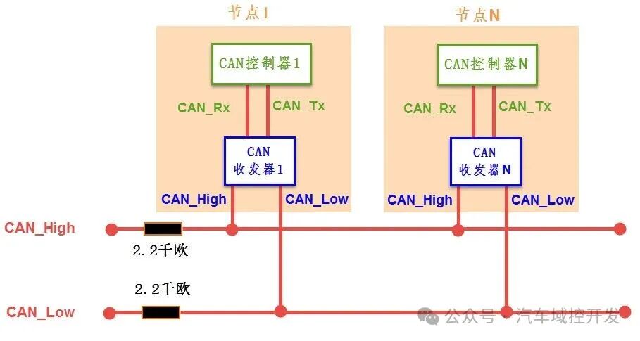
Image from doc.embedfire.com
From the above comparison, it can be concluded that the maximum transmission distance and maximum communication speed exhibit an inverse relationship as shown in the following diagram:
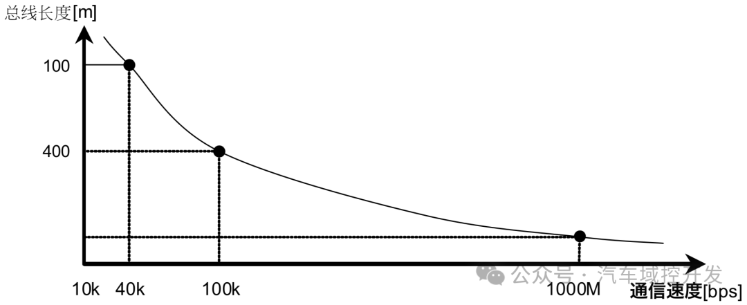
Image from Renesas
Differential Level Logic
Apart from the differences in communication speed/distance and network form, the level logic of the two standards also differs. Taking the high-speed CAN protocol as an example, when representing a recessive level (logic 1), the voltages on the <span>CAN_High</span> and <span>CAN_Low</span> lines are both <span>2.5V</span>, meaning their voltage difference is <span>VH-VL=0V</span>; while when representing a dominant level (logic 0), the voltage on <span>CAN_High</span> is <span>3.5V</span>, and the voltage on <span>CAN_Low</span> is <span>1.5V</span>, resulting in a voltage difference of <span>VH-VL=2V</span>. The table below shows the differential logic levels defined by the two standards:

Image from doc.embedfire.com
For example, when the CAN transceiver receives a low-level signal (logic 0) from the <span>CAN_Tx</span> line from the CAN controller, it will output <span>3.5V</span> on <span>CAN_High</span> and <span>1.5V</span> on <span>CAN_Low</span>, thus outputting a dominant level representing logic 0.
Reference Link
<span>[1]</span> CAN Communication: https://doc.embedfire.com/mcu/renesas/fsp_ra/zh/latest/doc/chapter41/chapter41.html#can-tja1042
If you have read this far, please give a like and follow to support me🙏, your support is the motivation for my continued creation!