 Arduino Sensor: HS-S01A Infrared SensorArduino Sensor: HS-S02P Infrared Sensor (Obstacle Avoidance)Arduino Sensor: HS-S03P Ultraviolet SensorArduino Sensor: HS-S05P Sound SensorArduino Sensor: HS-F07P Active BuzzerArduino Sensor: HS-S08P Flame SensorArduino Sensor: HS-S09LB Raindrop SensorArduino Sensor: HS-S09PC Soil Moisture Sensor
Arduino Sensor: HS-S10P Mist Sensor
Arduino Sensor: HS-S11-L Gas Sensor
Arduino Sensor: HS-S20P Ambient Light Sensor
Arduino Sensor: HS-S21P Tilt SensorArduino Sensor: HS-S22P Grayscale SensorArduino Sensor: HS-S24P Digital Temperature SensorArduino Sensor: HS-S26A Temperature and Humidity SensorArduino Sensor: HS-S28P Rotary Potentiometer
Arduino Sensor: HS-S31P Touch Sensor
Arduino Sensor: HS-S37PS Water Level Sensor
Arduino Sensor: HS-S38P Human Body Sensor
Arduino Sensor: HS-S40P Hall Magnetic Sensor
Arduino Sensor: HS-S45P Barometric Pressure Sensor
Arduino Sensor: HS-S46P Weighing Sensor
Arduino Sensor: HS-S59P Slot Photoelectric Sensor
Arduino Sensor: HS-S70P Heart Rate and Blood Oxygen Sensor
Arduino Sensor: Infrared Receiver Module
Arduino Sensor: Infrared Transmitter Module
Arduino Sensor: Clock Module
Arduino Sensor: Rotary Encoder Module
Arduino Sensor: Dual-axis Joystick Module
Arduino Sensor: Gyroscope Module
Arduino Sensor: Voice Broadcast Module
Arduino Sensor: Voice Recognition Control Module
Arduino Communication Module: Bluetooth Module
Arduino Power Module: Motor Driver Module
Arduino Control Module: Self-locking Button ModuleArduino Storage Module: SD Card Module
Arduino Control Module: Conductive Switch Module
Arduino Execution Module: Electromagnet ModuleArduino Detection Module: Ultrasonic Module
01Basic Knowledge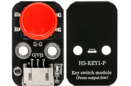 Model:HS-KEY1B-PName: Switch ModuleSeries: Human-Machine Interaction ModuleDescription: This is a digital input module that integrates a mechanical button and a pull-up resistor. It outputs high and low level signals through physical pressing actions, achieving human-machine interaction functions. It features sensitive triggering, sturdy structure, and anti-jitter circuit design, making it the most basic input component in electronic devices, widely used in scenarios such as function switching, parameter adjustment, and command confirmation.Usage Scenarios: Smart device control buttons (e.g., table lamp switch, fan speed control); children’s programming teaching tools (triggering different program logic through buttons); industrial control panels (device start/stop, mode switching); interactive art installations (pressing triggers light or sound effects); primary and secondary school science experiments (exploring the relationship between circuit continuity and signal changes), in line with the “Guidelines for General Education in Artificial Intelligence for Primary and Secondary Schools (2025 Edition)” practical requirements; assistive control devices designed for special populations (large buttons for easy operation).Disciplinary Integration: Physics, Mathematics, Materials Science , Information TechnologyEthical Education: Button design must consider inclusivity (suitable for different hand shapes and operational abilities); important operations must have a confirmation mechanism (to prevent accidental touches), reflecting humanistic care; classification and recycling of metal contacts and plastic shells in electronic waste must pay attention to environmental responsibility; overly simplified button interactions may reduce operational safety (e.g., emergency stop buttons must be prominently designed); the button layout of public devices should conform to ergonomic principles to reduce operational fatigue.Note: Images are sourced from the internet, and products are based on actual purchases.
02Technical Parameters
Working Principle:
The core of the module is a mechanical button, which achieves circuit connection and disconnection through a spring metal contact. When not pressed, the button is in an open state, and the pull-up resistor keeps the output high; when the button is pressed, the contact closes, connecting the output to GND, resulting in a low output; after releasing, the spring restores the contact, and the output returns to high. The module has a built-in 10kΩ pull-up resistor (which can be switched to pull-down mode via a jumper cap), allowing it to work stably without external circuits, and also integrates an RC filter circuit to reduce signal fluctuations caused by mechanical jitter..
Parameter Analysis:
G(GND): Power input negative/cathodeV (VCC): Power input positive/anode levelS(Signal): Signal output interfaceTrigger method: Low level trigger (default, pull-up mode)/ High level trigger (pull-down mode)Mechanical lifespan: ≥100,000 presses (pressing force 50±10g)Contact resistance: ≤50mΩRebound time: ≤10ms (mechanical jitter elimination)03Code Example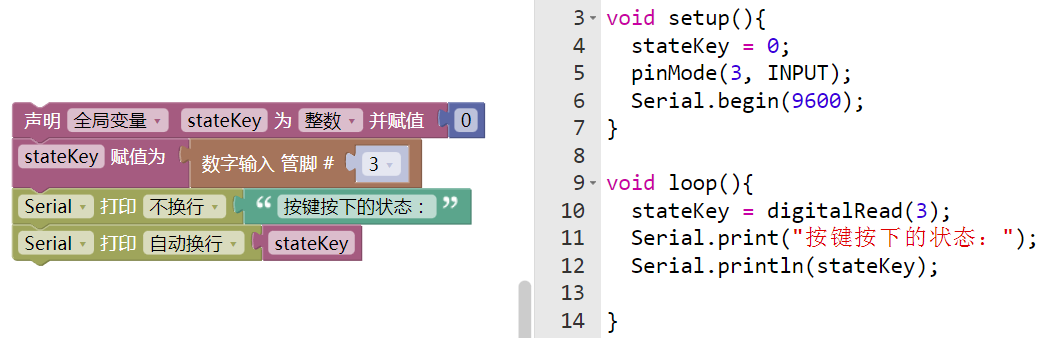
The connection pin is D3.
04Safety Measures
1. Power off before wiring, confirm VCC voltage (3.3V-5V), excessive voltage may burn the module circuit;
2. When pressing the button, apply moderate force (≤60g), excessive force may deform and damage the mechanical contact;
3. Avoid using in humid environments, moisture can cause contact oxidation and poor connection;
4. When soldering, the soldering iron temperature should be ≤300℃, and soldering time should be ≤3 seconds to prevent high temperature damage to pins and buttons;
5. If the module is used in children’s devices, ensure the buttons are securely installed to prevent detachment and accidental swallowing;
6. If the signal is unstable during debugging, check for poor contact (e.g., loose pins) or external electromagnetic interference;
7. Avoid pressing the button during long-term storage to prevent spring fatigue and loss of rebound function.
05Extensions
Students can try the following methods:
1. Create a “Password Lock Device”: Link with HS-F12P RGB-LED strip, press the correct preset button sequence (e.g., 3 short presses + 1 long press), LED shows green, otherwise shows red;2. Build a “Counter”: Combine with OLED screen, record the number of button presses and display it, long press for 2 seconds to reset;3. Design a “Music Player”: Work with HS-F02P Buzzer, short press to switch notes, long press to play/pause, achieving a simple electronic piano;4. Develop a “Mode Switching Controller”: Control HS-F04P Motor Driver Module through multiple presses (1 time / 2 times / 3 times) to achieve motor forward/reverse/stop functions.

— Previous Recommendations —