
Click the blue text
1. Introduction
1. Concept
The SPI (Serial Peripheral Interface) bus protocol is a full-duplex synchronous serial bus communication protocol used for data transmission between integrated circuits. The SPI bus typically consists of one master device and multiple slave devices, each slave device has a separate chip select signal, and it can operate at hundreds of MHz. Generally, SPI requires four lines, but it can also work with three lines.
2. Features
-
Synchronous Communication: SPI is a synchronous communication protocol where data transmission is controlled by the clock signal (SCLK) provided by the master device, ensuring synchronized data transmission. -
Full-Duplex Communication: SPI supports full-duplex communication, allowing the master and slave devices to send and receive data simultaneously. -
Multi-Slave Support: A master device can connect to multiple slave devices, selecting a specific slave device for communication through the chip select signal (Chip Select, CS). -
Simple Hardware Connection: Compared to other protocols like I²C, the hardware connection of SPI is relatively simple and does not require complex handshake signals.
Advantages:
SPI protocol is widely used in scenarios requiring high-speed data transmission and reliability, such as:
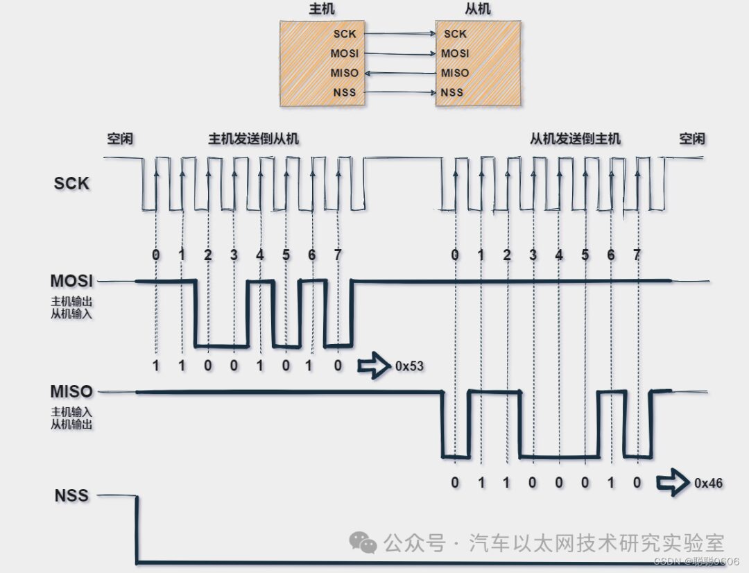
2. Communication Principle
SPI generally consists of four pins (one master and one slave):
Different chip manufacturers have different naming conventions, and in addition, there are:
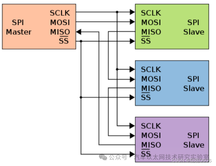
Figure 1
3. Communication Characteristics
SPI is a very flexible communication protocol; we can configure its clock polarity, clock phase, etc.
1. Clock Frequency
The clock frequency of SPI refers to the frequency of the clock signal used for synchronizing data transmission. It determines the speed of data transmission. The configuration of the clock frequency needs to consider the hardware limitations of the master and slave devices and the communication distance.
Configuring the SPI clock frequency mainly involves the following steps:
Clock polarity is used to set the level state of the clock when idle,
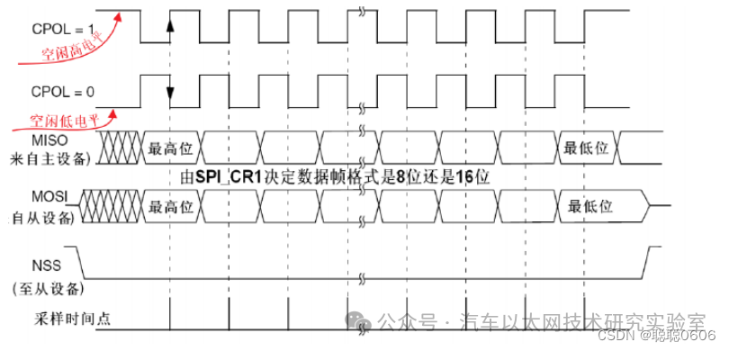
Clock phase is used to set at which clock edge the data line is sampled,
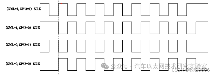
Now that we know what phase and polarity are, we can classify SPI into four modes based on their different combinations. The master and slave must operate in the same mode to communicate normally. In practice, “Mode 0” and “Mode 3” are commonly used.
|
SPI Mode |
CPOL |
CPHA |
Idle CLK Level |
Sampling Moment |
|
0 |
0 |
0 |
Low Level |
Odd Edge |
|
1 |
0 |
1 |
Low Level |
Even Edge |
|
2 |
1 |
0 |
High Level |
Odd Edge |
|
3 |
1 |
1 |
High Level |
Even Edge |
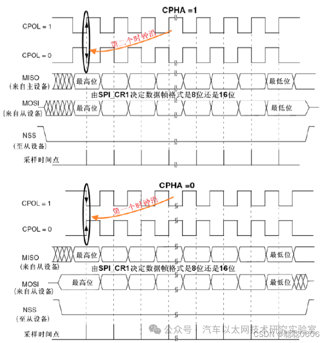
Mode0: CPOL=0, CPHA=0: In this case, when idle, SCLK is low, data is sampled on the first edge, which is the transition of SCLK from low to high, so data is sampled on the rising edge (data preparation), and data is sent on the falling edge.
Mode1: CPOL=0, CPHA=1: In this case, when idle, SCLK is low, data is sent on the first edge, which is the transition of SCLK from low to high, so data is sampled on the falling edge, and data is sent on the rising edge.
Mode2: CPOL=1, CPHA=0: In this case, when idle, SCLK is high, data is sampled on the first edge, which is the transition of SCLK from high to low, so data is sampled on the falling edge, and data is sent on the rising edge.
Mode3: CPOL=1, CPHA=1: In this case, when idle, SCLK is high, data is sent on the first edge, which is the transition of SCLK from high to low, so data is sampled on the rising edge, and data is sent on the falling edge.
The specific sampling data is shown in Figure 5:
5. Multi-Master Mode
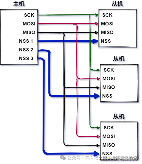
As mentioned earlier, the SPI bus must have one master and can have multiple slaves. The specific connection methods to the SPI bus are as follows: multiple chip selects and daisy chaining.
(1) Multiple Chip Selects
① Typically, each slave requires a separate CS line.
② To communicate with a specific slave, the corresponding CS signal line can be pulled low, while keeping the states of other CS signal lines high; if two CS signal lines are pulled low simultaneously, it may cause garbled data since both slaves may attempt to transmit data on the same MISO line, resulting in corrupted received data.
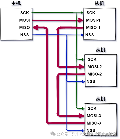
(2) Daisy Chain
Daisy chaining is a common connection topology used to serially connect multiple devices, allowing each device to connect with the previous and next devices. Daisy chaining is widely used in many applications, such as serial communication, computer buses, audio devices, and LED light strings.
Characteristics:
-
Serial connection: Each device is connected to the next and previous devices through input and output ports. -
Single channel: Data is transmitted through a single channel, sequentially through each device. -
Simplified wiring: Compared to star topology, daisy chaining reduces wiring complexity, as independent connections from each device to the central node are not required. -
Easy expansion: Adding or removing devices is relatively simple, just connect or disconnect the corresponding device.
-
Simplified wiring: Reduces the complexity of physical connections. -
Easy expansion: Devices can be easily added or removed.
-
Accumulated delay: Each device adds data transmission delay. -
Reliability issues: If one device in the chain fails, it may affect the communication of the entire chain.
4. Programming Implementation
Taking the domestic chip ZhiXin Semiconductor’s Z20K118 chip as an example, the example program for using the SPI master to transmit and receive data is provided in the resources:
The hardware block diagram is shown below
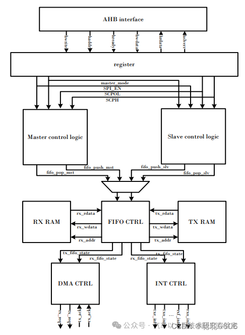
The software code is as follows
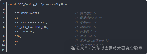
1. SPI Structure Configuration
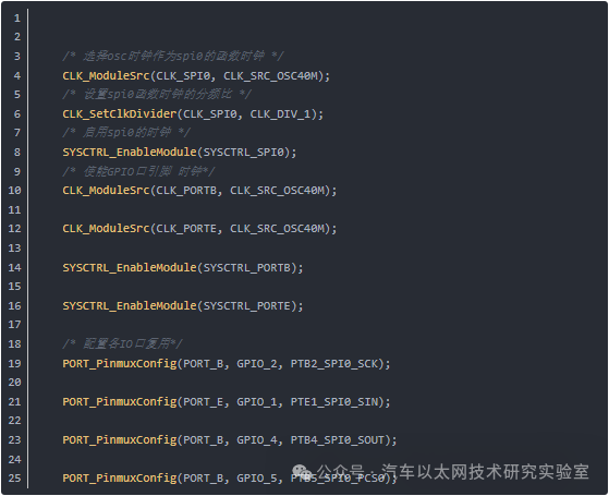
2. System Initialization
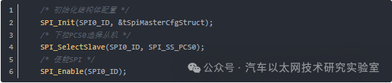
3. Enable SPI and pull down PCS to select the slave node
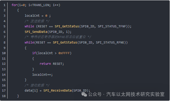
4. Send Data
5. Comparison of Three Types of SPI
The three types of SPI usually refer to Standard SPI, Dual SPI, and Queued SPI. The Standard SPI has been introduced, so we will mainly discuss the latter two types of SPI and their differences.
1. Dual SPI
Dual SPI is an enhanced SPI communication mode mainly used to increase data transmission rates. It adds data transmission channels so that more data can be transmitted in each clock cycle.
Dual SPI is only applicable to SPI Flash, not to all SPI peripherals. For SPI Flash, full-duplex is not commonly used, so it extends the use of MOSI and MISO to work in half-duplex mode, doubling the data transmission. In other words, for Dual SPI Flash, a command byte can be sent to enter dual mode, making MOSI SIO0 (serial io 0) and MISO SIO1 (serial io 1), allowing 2 bits of data to be transmitted in one clock cycle, effectively doubling the data transmission.
Features
-
Dual-channel data transmission: Uses two data lines to transmit data simultaneously, usually MOSI and MISO transmitting data together. -
Higher transmission rate: Dual SPI can transmit more data than Standard SPI at the same clock frequency. -
Higher hardware requirements: Requires master and slave devices that support Dual SPI mode.
Queued SPI is an advanced SPI communication mode, typically used in scenarios requiring efficient management of multiple SPI transmission transactions. It adds hardware queue functionality on top of Standard SPI, allowing multiple SPI transmission transactions to be pre-configured, and the master can automatically execute these transactions sequentially.
Queued SPI is the abbreviation for Queued SPI, which is based on Dual SPI and adds two I/O lines (SIO2, SIO3) to transmit 4 bits in one clock cycle.
Features
-
Hardware queue: Allows pre-configuration of multiple transmission transactions, which are executed automatically by hardware. -
Efficient management: Reduces CPU intervention and improves data transmission efficiency. -
Suitable for complex scenarios: Particularly suitable for applications requiring frequent and complex SPI transmissions, such as memory access.
3. Differences Among the Three
(4) QSPI: Standard 4-wire connection, half-duplex, 4 data lines, bidirectional switching.
|
Feature |
Standard SPI |
Dual SPI |
Queued SPI |
|
Data Channel |
Single Channel |
Dual Channel |
Single or Dual Channel |
|
Data Rate |
Regular |
Higher |
Efficient Management |
|
Hardware Complexity |
Simple |
Requires Dual SPI supporting devices |
Requires QSPI supporting devices |
|
Transmission Rate |
Normal |
Higher |
Highest |
|
Application Scenario |
General SPI Communication |
High-speed Data Transmission |
Complex, Frequent SPI Transmission |
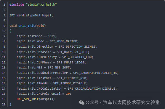
① Standard SPI code configuration
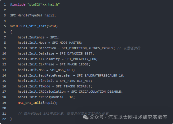
② Dual SPI code configuration
When configuring Dual SPI, it is necessary to additionally set the dual-channel mode for the data lines:
③ QSPI code configuration
QSPI configuration is relatively complex and requires configuring queue management and multi-channel modes