Understanding the Meaning of Each JTAG Pin

Do you understand the meaning of each JTAG pin?
JTAG has 10-pin, 14-pin, and 20-pin versions. Although the number of pins and the arrangement order differ, some of the pins are the same. The definitions of each pin are as follows.
1. Pin Definitions
Test Clock Input (TCK) —– Required 1
TCK is a mandatory requirement in the IEEE1149.1 standard.TCK provides an independent, basic clock signal for TAP operations, and all TAP operations are driven by this clock signal.
Test Mode Selection Input (TMS) —– Required 2
The TMS signal is valid on the rising edge of TCK.TMS is a mandatory requirement in the IEEE1149.1 standard.The TMS signal controls the state transitions of the TAP state machine.Through the TMS signal, the TAP can switch between different states.
Test Data Input (TDI) —– Required 3
TDI is a mandatory requirement in the IEEE1149.1 standard.TDI is the data input interface.All data to be input into a specific register is serially input bit by bit through the TDI interface (driven by TCK).
Test Data Output (TDO) —– Required 4
TDO is a mandatory requirement in the IEEE1149.1 standard.TDO is the data output interface.All data to be output from a specific register is serially output bit by bit through the TDO interface (driven by TCK).
Test Reset Input (TRST) —- Optional 1
This signal interface is optional in the IEEE 1149.1 standard and is not mandatory.TRST can be used to reset (initialize) the TAP controller.Since TAP can also be reset (initialized) through TMS, there is a distinction between four-wire JTAG and five-wire JTAG.
(VTREF) —– Required 5
The reference voltage level of the interface signal is generally directly connected to Vsupply.This can be used to determine the logic level used by the ARM JTAG interface (for example, 3.3V or 5.0V?).
Return Test Clock (RTCK) —- Optional 2
Optional, a clock signal fed back from the target to the emulator, used to synchronize the generation of the TCK signal; if not used, it should be grounded.
System Reset (nSRST) —- Optional 3
Optional, connected to the system reset signal on the target board, can directly reset the target system.It can also detect the reset status of the target system; to prevent false triggering, appropriate pull-up resistors should be added on the target side.
USER IN
User-defined input.Can be connected to an IO to receive control from the host computer.
USER OUT
User-defined output.Can be connected to an IO to provide feedback on a status to the host computer.
Since JTAG is often connected using ribbon cables, to enhance anti-interference capability, a ground line is added between each signal line, resulting in this 20-pin interface.However, in practice, RTCK, USER IN, and USER OUT are generally not used, so there is also a 14-pin interface.For actual development applications, due to stable laboratory power supply and good electromagnetic environment, interference is minimal.
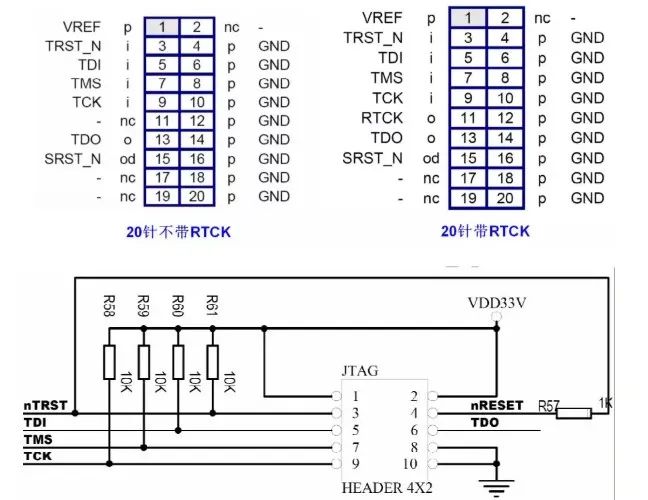
2. Correspondence Between Pin Names and Numbers for 20, 14, and 10-pin JTAG
It is worth noting that different IC companies define their own proprietary JTAG headers for downloading or debugging programs.The signal arrangements for commonly used 20, 14, and 10-pin JTAG in embedded systems are as follows:
Understanding the Meaning of Each JTAG Pin
It should be noted that the pin names of the above JTAG header refer to the IC.For example, the TDI pin indicates that this pin should be connected to the TDI pin on the IC, rather than indicating that data enters the download cable from this pin.
In fact, a 10-pin connection only requires 4 wires; pin 4 is a self-loop and does not need to be connected, while pins 1 and 2 are both connected to pin 1, and pins 8 and 10 are connected to GND, which can also be left unconnected.
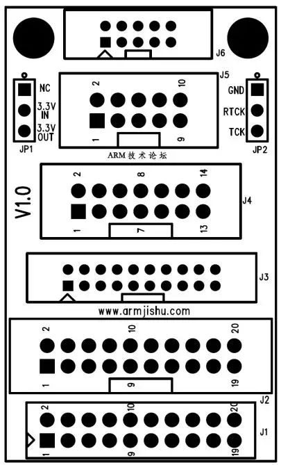
Attached is the circuit of the adapter board:
Understanding the Meaning of Each JTAG Pin

Understanding the Meaning of Each JTAG Pin

Disclaimer:This article is original by the author, and the content represents the author’s personal views. The Electronics Enthusiast Network reproduces it only to convey a different perspective and does not represent the Electronics Enthusiast Network’s endorsement or support of this view. If there are any objections, please contact the Electronics Enthusiast Network.
More Exciting Articles to Read
  • Huawei 5G Chips for Sale for the First Time! 5G Modules Penetrate Multiple Industries!

  • In High Demand, Handheld Infrared Thermometers Become the First Hot Product of 2020!

  • Global Mobile Giants Are Layouting, 2020 Will Be the Year of GaN!

  • LG Asks Employees Not to Come to Work for Two Weeks to Control the Pandemic; Intel Launches 10nm Base Station Chip…

  • Awesome! 22 Animated Diagrams of Electrical Components!

Leave a Comment