Failure phenomenon: A “San’an” brand low-speed electric vehicle experienced a malfunction when the driver mistakenly disconnected the air switch controlling the main power supply while going downhill, causing the brushless DC motor to generate back electromotive force due to overspeed that could not be absorbed by the battery, resulting in damage to the controller due to overvoltage. Analysis and repair: Upon opening the controller, it was found that 8 power MOSFETs had exploded, and one surface-mounted transistor 8550 had shorted. After replacing the damaged components, it still failed to work, indicating that the fault was not resolved. The vehicle is equipped with 4 Shandong “Luwawa” brand 12V-170 type (100AH) lead-acid batteries. The motor has a rated power of 1000W, and the controller is a product of Xuzhou Kaiyuan Electronic Technology Co., Ltd. The controller contains 24 TO-220 packaged power MOSFETs, operates at a voltage of 48V, limits current to 59A, has a phase angle of 120 degrees, and includes a reverse function. I have several salvaged controllers available, each costing 10 to 15 yuan, which could reduce repair costs. After comparison, the controllers used on ordinary electric tricycles have the same voltage, phase angle, reverse function, and four-wheel vehicles but only use 12 MOSFETs, limiting current to 28A with a rated power of 500W. If we upgrade from 12 to 24 transistors, the current doubles, and the power is naturally sufficient. Directly paralleling two 500W electric vehicle controllers to achieve 1000W is not feasible, as it cannot guarantee that both controllers will be perfectly synchronized, leading to inevitable MOSFET failure.

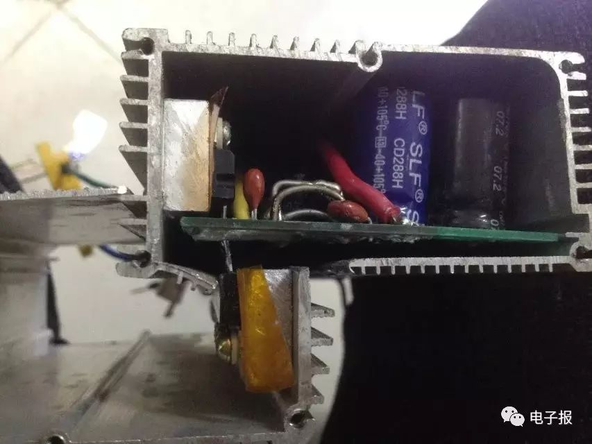
First, combine the two controllers into one; the signal and driving circuit can only use one, and the end power MOSFETs should be used in parallel. To avoid MOSFET failure, the parallel power MOSFETs must have the same or similar parameters as the original ones, and the pins should be as close to the power supply filter capacitor as possible, ideally without leads. To achieve a solid connection, simple soldering, no leads, and reliable operation, the only method is to solder the 12 parallel MOSFETs on the back of the original 12 MOSFETs on the controller circuit board. Since the packaging of the original and parallel 12 MOSFETs is the same and the spacing is identical, this achieves one-to-one correspondence for gate, drain, and source soldering. Second, double the current sampling resistor’s limiting value; the current sampling resistor on this controller circuit board uses copper wire, which is easy to identify, as shown in Figure 1. Originally there were 2 wires, and now we need to connect 2 more in parallel to reduce the sampling resistor’s resistance by half. Of course, we can also add solder on the original copper wire to reduce resistance; measuring with a milliohm meter during modification will yield more accurate results. Third, the positive and negative power supply copper foil lines on the controller circuit board should be appropriately thickened using the solder piling method. The board has two 1000μF/63V filter capacitors, and we should install another one to enhance the filtering function. The heat sinks of the MOSFETs installed in opposite orientations are not in the same plane; the aluminum heat sinks of both controllers should be cut open with an angle grinder and installed in opposite orientations, as seen in Figure 2. In practice, due to the size limitation of the controller, even if 24 MOSFETs are installed in the same plane, it would not fit, and circuit connections would be difficult. In the combined controller, only the MOSFETs and aluminum heat sinks from the other controller’s circuit board are needed. If there are larger current MOSFETs with the same package available, like replacing 75NF75 (75V/75A) with IRF3077 (75V/210A) or IRF3077 (75V/180A), it would save time and effort without increasing the number of transistors. [Note] If the small power controller does not have sufficient heat dissipation, adding a fan or using a larger aluminum casing can improve heat dissipation. Of course, increasing both the number of transistors and their parameters will yield better results. The assembled controller simulated test run showed no issues, and the road test results were satisfactory, indicating that the modification approach is feasible. Using a Hall effect coulometer to observe the driving current: the maximum current on flat roads is around 28A, with 55A during rapid acceleration and uphill, and a maximum of 22A when the motor recharges the battery while coasting downhill. At a temperature of 12°C, after continuous driving for 50 kilometers in mountainous, hilly, and flat highway conditions, the controller’s outer casing remained cool to the touch, indicating good modification results. To ensure worry-free driving, it makes sense for some drivers to carry a spare controller, as the likelihood of sudden failure of the electric vehicle battery within its lifespan is low, and under normal load conditions, the motor is also less likely to fail. Additionally, low-speed electric vehicles do not have a neutral gear; if the controller fails, the electromagnetic resistance makes pushing the vehicle difficult, and the three-phase lines of the motor must be disconnected before towing, making a controller failure quite troublesome.
◇ Hubei Qiu Chengsheng