
Click the blue text
Follow us
1. Introduction to I2C
-
The I2C communication protocol (Inter-Integrated Circuit) was developed by Philips. Due to its fewer pins, simple hardware implementation, and strong scalability, it does not require external transceivers for communication protocols like USART or CAN, and is now widely used for communication between multiple integrated circuits (ICs) within a system.
-
I2C is a half-duplex communication protocol.
-
I2C has only two bidirectional communication lines: one is the clock line SCL, and the other is the data line SDA.
-
The I2C bus is connected to the power supply through pull-up resistors, and when the bus is idle, both lines are at a high level. The SCL and SDA lines between devices are in a “wired AND” relationship.
2. I2C Timing
1. Stability of Data Bits
-
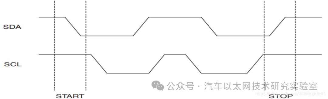
When I2C is transmitting data, the data on the SDA line must remain stable when the SCL clock line is high. The data on the SDA line can only change when the SCL clock line is low.
2. Start and Stop Signals
-
Start Signal: When the SCL clock line is high, the SDA data line transitions from high to low (falling edge).
-
Stop Signal: When the SCL clock line is high, the SDA data line transitions from low to high (rising edge).
3. Data Transmission Format
(1) Byte Transmission and Acknowledgment
-
Each byte must be 8 bits.
-
During data transmission, the highest bit is sent first, followed by the lowest bit.
-
Each byte must be followed by an acknowledgment bit (i.e., after the master sends a byte of data to the slave, it must wait for the slave’s acknowledgment).
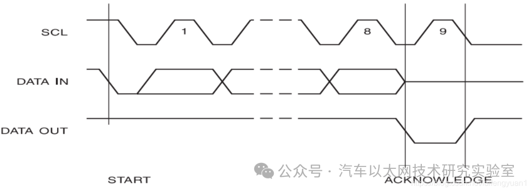
(2) Acknowledgment Bit
-
Acknowledgment: When the master releases the SDA data line (at this point, the SDA line is high), the slave pulls the SDA line low to indicate acknowledgment.
-
No Acknowledgment: When the master releases the SDA data line (at this point, the SDA line is high), the slave keeps the SDA line high to indicate no acknowledgment.
-
When the slave does not acknowledge the master, it must pull the SDA line high. The master then needs to generate a stop signal to terminate the data transmission.
-
When the master has finished reading the data sent by the slave, it needs to send an acknowledgment via SDA and then send a stop signal.
(3) Acknowledgment Setting Process: First, pull SCL low – then pull SDA low (SDA can only change data when SCL is low) – then pull SCL high (when SCL is high, the data on SDA is valid) – then pull SCL low (indicating the end of the 9th cycle).
4. Data Frame Format
-
The data signals transmitted on the I2C bus are broad, including both address signals and actual data signals. After the start signal, a slave address (7 bits) must be transmitted, with the 8th bit indicating the direction of data transfer (R/W).
(1) Master Sending Data: Start Signal – Slave Address (1-7 bits for slave address, 8th bit for write direction set to 0) – Wait for Slave Acknowledgment – Send Data – Wait for Slave Acknowledgment – (Timeout or Slave No Acknowledgment or Data Transmission Complete) Stop Signal.
(2) Master Receiving Data: Start Signal – Slave Address (1-7 bits for slave address, 8th bit for read direction set to 1) – Wait for Slave Acknowledgment – Receive Data – Send Acknowledgment to Slave – (After receiving all data) Send No Acknowledgment – Master sends Stop Signal to end data transmission.

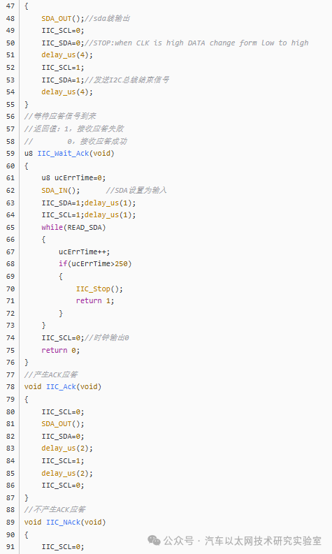
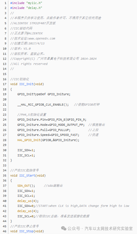
3. Software I2C Example
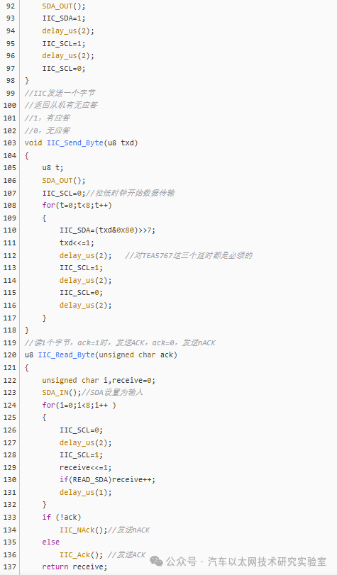
(1) Example I2C Code from Point Atom
(2) Explanation of Some Code in AT24C02
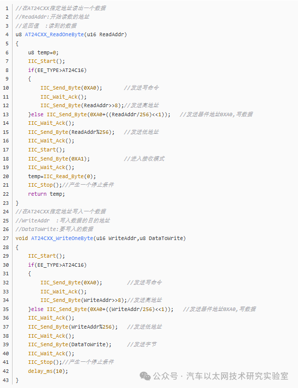
First, we can look at the code above. Many people may have questions about IIC_Send_Byte(0XA0+((ReadAddr/256)<<1)). In fact, this line is not much different from IIC_Send_Byte(0XA0); IIC_Wait_Ack(); IIC_Send_Byte(ReadAddr>>8); as long as the timing given in AT24Cxx is followed, communication with AT24Cxx can be achieved.
4. Using STM32 Hardware I2C (HAL Library)
The I2C function interfaces in the HAL library are very simple and easy to use. To understand how to use the STM32 I2C interface in detail, we only need to check the I2C header file in the HAL library.
(1) I2C Function Interfaces in HAL Library
-
/* IO operation functions ****************************************************/
-
/******* Blocking mode: Polling */
-
HAL_StatusTypeDef HAL_I2C_Master_Transmit(I2C_HandleTypeDef *hi2c, uint16_t DevAddress, uint8_t *pData, uint16_t Size, uint32_t Timeout);
-
HAL_StatusTypeDef HAL_I2C_Master_Receive(I2C_HandleTypeDef *hi2c, uint16_t DevAddress, uint8_t *pData, uint16_t Size, uint32_t Timeout);
-
HAL_StatusTypeDef HAL_I2C_Slave_Transmit(I2C_HandleTypeDef *hi2c, uint8_t *pData, uint16_t Size, uint32_t Timeout);
-
HAL_StatusTypeDef HAL_I2C_Slave_Receive(I2C_HandleTypeDef *hi2c, uint8_t *pData, uint16_t Size, uint32_t Timeout);
-
HAL_StatusTypeDef HAL_I2C_Mem_Write(I2C_HandleTypeDef *hi2c, uint16_t DevAddress, uint16_t MemAddress, uint16_t MemAddSize, uint8_t *pData, uint16_t Size, uint32_t Timeout);
-
HAL_StatusTypeDef HAL_I2C_Mem_Read(I2C_HandleTypeDef *hi2c, uint16_t DevAddress, uint16_t MemAddress, uint16_t MemAddSize, uint8_t *pData, uint16_t Size, uint32_t Timeout);
-
HAL_StatusTypeDef HAL_I2C_IsDeviceReady(I2C_HandleTypeDef *hi2c, uint16_t DevAddress, uint32_t Trials, uint32_t Timeout);
-
/******* Non-Blocking mode: Interrupt */
-
HAL_StatusTypeDef HAL_I2C_Master_Transmit_IT(I2C_HandleTypeDef *hi2c, uint16_t DevAddress, uint8_t *pData, uint16_t Size);
-
HAL_StatusTypeDef HAL_I2C_Master_Receive_IT(I2C_HandleTypeDef *hi2c, uint16_t DevAddress, uint8_t *pData, uint16_t Size);
-
HAL_StatusTypeDef HAL_I2C_Slave_Transmit_IT(I2C_HandleTypeDef *hi2c, uint8_t *pData, uint16_t Size);
-
HAL_StatusTypeDef HAL_I2C_Slave_Receive_IT(I2C_HandleTypeDef *hi2c, uint8_t *pData, uint16_t Size);
-
HAL_StatusTypeDef HAL_I2C_Mem_Write_IT(I2C_HandleTypeDef *hi2c, uint16_t DevAddress, uint16_t MemAddress, uint16_t MemAddSize, uint8_t *pData, uint16_t Size);
-
HAL_StatusTypeDef HAL_I2C_Mem_Read_IT(I2C_HandleTypeDef *hi2c, uint16_t DevAddress, uint16_t MemAddress, uint16_t MemAddSize, uint8_t *pData, uint16_t Size);
-
HAL_StatusTypeDef HAL_I2C_Master_Seq_Transmit_IT(I2C_HandleTypeDef *hi2c, uint16_t DevAddress, uint8_t *pData, uint16_t Size, uint32_t XferOptions);
-
HAL_StatusTypeDef HAL_I2C_Master_Seq_Receive_IT(I2C_HandleTypeDef *hi2c, uint16_t DevAddress, uint8_t *pData, uint16_t Size, uint32_t XferOptions);
-
HAL_StatusTypeDef HAL_I2C_Slave_Seq_Transmit_IT(I2C_HandleTypeDef *hi2c, uint8_t *pData, uint16_t Size, uint32_t XferOptions);
-
HAL_StatusTypeDef HAL_I2C_Slave_Seq_Receive_IT(I2C_HandleTypeDef *hi2c, uint8_t *pData, uint16_t Size, uint32_t XferOptions);
-
HAL_StatusTypeDef HAL_I2C_EnableListen_IT(I2C_HandleTypeDef *hi2c);
-
HAL_StatusTypeDef HAL_I2C_DisableListen_IT(I2C_HandleTypeDef *hi2c);
-
HAL_StatusTypeDef HAL_I2C_Master_Abort_IT(I2C_HandleTypeDef *hi2c, uint16_t DevAddress);
-
/******* Non-Blocking mode: DMA */
-
HAL_StatusTypeDef HAL_I2C_Master_Transmit_DMA(I2C_HandleTypeDef *hi2c, uint16_t DevAddress, uint8_t *pData, uint16_t Size);
-
HAL_StatusTypeDef HAL_I2C_Master_Receive_DMA(I2C_HandleTypeDef *hi2c, uint16_t DevAddress, uint8_t *pData, uint16_t Size);
-
HAL_StatusTypeDef HAL_I2C_Slave_Transmit_DMA(I2C_HandleTypeDef *hi2c, uint8_t *pData, uint16_t Size);
-
HAL_StatusTypeDef HAL_I2C_Slave_Receive_DMA(I2C_HandleTypeDef *hi2c, uint8_t *pData, uint16_t Size);
-
HAL_StatusTypeDef HAL_I2C_Mem_Write_DMA(I2C_HandleTypeDef *hi2c, uint16_t DevAddress, uint16_t MemAddress, uint16_t MemAddSize, uint8_t *pData, uint16_t Size);
-
HAL_StatusTypeDef HAL_I2C_Mem_Read_DMA(I2C_HandleTypeDef *hi2c, uint16_t DevAddress, uint16_t MemAddress, uint16_t MemAddSize, uint8_t *pData, uint16_t Size);
-
HAL_StatusTypeDef HAL_I2C_Master_Seq_Transmit_DMA(I2C_HandleTypeDef *hi2c, uint16_t DevAddress, uint8_t *pData, uint16_t Size, uint32_t XferOptions);
-
HAL_StatusTypeDef HAL_I2C_Master_Seq_Receive_DMA(I2C_HandleTypeDef *hi2c, uint16_t DevAddress, uint8_t *pData, uint16_t Size, uint32_t XferOptions);
-
HAL_StatusTypeDef HAL_I2C_Slave_Seq_Transmit_DMA(I2C_HandleTypeDef *hi2c, uint8_t *pData, uint16_t Size, uint32_t XferOptions);
-
HAL_StatusTypeDef HAL_I2C_Slave_Seq_Receive_DMA(I2C_HandleTypeDef *hi2c, uint8_t *pData, uint16_t Size, uint32_t XferOptions);
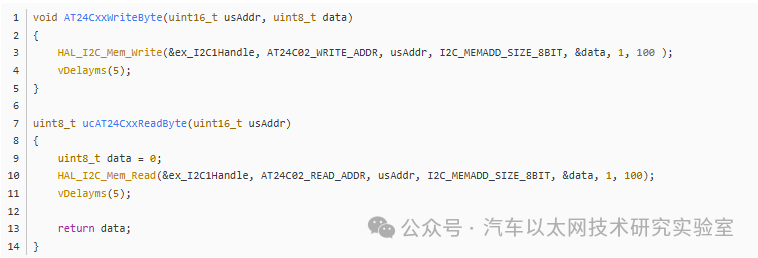
(2) Example of Encapsulating Read and Write Functions for AT24C02 Using HAL Library
5. Common I2C Debugging Techniques
(1) Check if the slave acknowledges: Send a start signal, send the slave address, and then check if the slave responds correctly. (This is the simplest method, assuming the slave address and other information are correct.)
Note: Generally, the first 7 bits of the I2C slave address are the slave address, and the 8th bit is the read/write bit.


*Disclaimer: This article is original or forwarded by the author. If it inadvertently infringes on someone’s intellectual property, please inform us for deletion.The above images and text are sourced from the internet. If there is any infringement, please contact us in a timely manner, and we will delete it within 24 hours.The content of the article reflects the author’s personal views, and the Automotive Ethernet Technology Research Laboratory reprints it only to convey a different perspective, which does not represent the Automotive Ethernet Technology Research Laboratory’s agreement or support for this view. If there are any objections, please feel free to contact the Automotive Ethernet Technology Research Laboratory.
Original link:
https://blog.csdn.net/laifengyuan1/article/details/109744804