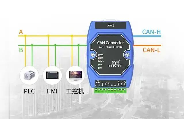
1. What is the basic working principle of the CAN bus?
The CAN bus is a multi-master serial communication protocol primarily used in automotive and industrial control. It transmits data through differential signals (CAN_H and CAN_L) and has a high anti-interference capability.
The CAN bus employs a non-destructive bit arbitration mechanism to ensure that high-priority messages are transmitted first. Nodes communicate by sending messages with identifiers, which not only indicate the content of the message but also determine its priority. 2. What is the role of the identifier (ID) in the CAN bus?
The identifier (ID) in the CAN bus has two main functions: 1. Message identification: uniquely identifies the content and type of the message.
2. Priority determination: the smaller the ID value, the higher the priority. During bus arbitration, higher priority messages are transmitted first, while lower priority nodes automatically withdraw from sending and wait to retry after the bus is idle. 3. How does the CAN bus achieve error detection and correction?
The CAN bus implements error detection and correction through the following mechanisms: 1. CRC check: each message frame contains a 15-bit CRC code, and the receiving node recalculates the CRC and compares it with the received CRC.
2. Frame check: checks whether the frame format, bit stuffing rules, etc., comply with standards.
3. ACK confirmation: the sending node waits for an ACK confirmation from the receiving node; if no ACK is received, it will resend.
4. Error frame: nodes that detect an error will send an error frame to notify other nodes to discard the current message. 4. What is bit stuffing in the CAN bus? Why is bit stuffing necessary? Bit stuffing is the insertion of a complementary bit after every five consecutive identical bits during data transmission in the CAN bus. Its purposes are: 1. Synchronization: to ensure that the clocks of the sending and receiving nodes are synchronized. 2. Error detection: stuffed bits can help detect interference or faults on the bus.
5. What types of frames are there in the CAN bus? What are their functions?
There are several types of frames in the CAN bus: 1. Data frame: used for nodes to send data, containing identifier, control field, data field, CRC field, etc.
2. Remote frame: used to request other nodes to send specific data; its structure is similar to that of the data frame but does not contain the data field.
3. Error frame: used to notify errors on the bus, consisting of an error flag and an error delimiter.
4. Overload frame: used to request a delay when a node cannot process data; its structure is similar to that of the error frame.
5. Inter-frame: used to separate different data frames or remote frames. 6. How does the arbitration mechanism work in the CAN bus? The CAN bus uses a non-destructive bit arbitration mechanism, which works as follows: 1. Simultaneous sending: when multiple nodes send messages simultaneously, the bus performs arbitration using the identifier (ID).
2. Bit comparison: nodes listen to the bus level while sending the ID; if the bit sent does not match the bus level, they withdraw from arbitration.
3. Priority: the smaller the ID value, the higher the priority. Nodes with higher priority continue to send, while lower priority nodes withdraw and wait to retry after the bus is idle. 7. What are the error states in the CAN bus, and how do they transition? CAN nodes have three error states: 1. Active error state: the node can normally send and receive messages and sends an active error flag when an error is detected.
2. Passive error state: the node has a high error count and sends a passive error flag when an error is detected, increasing the sending interval.
3. Bus-off state: when the node’s error count reaches the limit, it stops sending and receiving messages and must be restarted or reset to recover. Transition rules: when sending or receiving errors, the error count increases; when successfully sending or receiving, the error count decreases.
When the sending error count exceeds 127, the node enters the passive error state; when it exceeds 255, it enters the bus-off state.