
The Linux driver introductory course is now online and will be continuously updated!
https://www.bilibili.com/cheese/play/ss635583370

01
Introduction to the I2C Bus
The I2C bus protocol (Inter-Integrated Circuit) is a serial communication bus protocol proposed by Philips (now NXP), primarily used for low-speed, short-distance communication between a master chip and various peripherals (such as EEPROMs, sensors, RTCs, GPIO expansion chips, etc.).
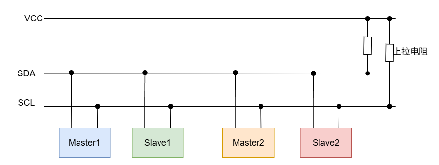
-
SCL (Serial Clock): The clock signal generated by the master device.
-
SDA (Serial Data): The data signal, which is bi-directional.
-
Both lines are designed as open-drain, requiring pull-up resistors to ensure “wired AND” logic.
02
I2C Modes
Currently, there are 5 modes of I2C, or 5 communication speeds.
-
Standard Mode: 100kbps
-
Fast Mode: 400kbps
-
Fast-Plus Mode: 1Mbps
-
High-Speed Mode: 1.7Mbps or 3.4Mbps
-
Ultra-Fast Mode: 5Mbps (one-way transmission)
*The rates mentioned refer to the SCL clock frequency.
03
I2C Addressing
I2C supports 7-bit and 10-bit addressing, with 7-bit addresses being more commonly used.
04
I2C Protocol
4.1. Signal Types
The I2C protocol has several signal types: start signal, stop signal, acknowledgment signal, and non-acknowledgment signal.
(1) Start and Stop Signals
Start Signal: When SCL is high, SDA transitions from high to low. Stop Signal: When SCL is high, SDA transitions from low to high.
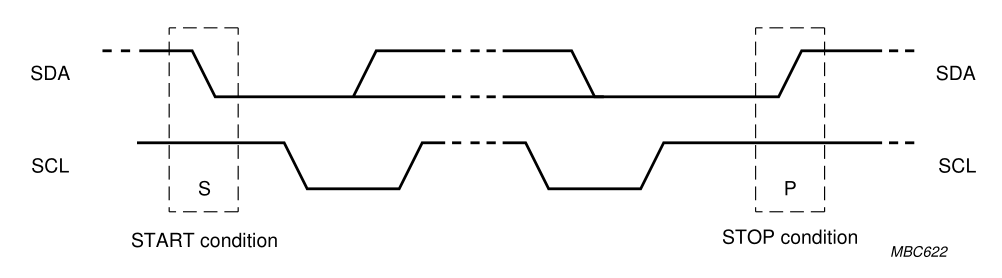
In idle state, both SDA and SCL are high, which is why pull-up resistors are necessary in hardware design.
(2) Acknowledgment Signal
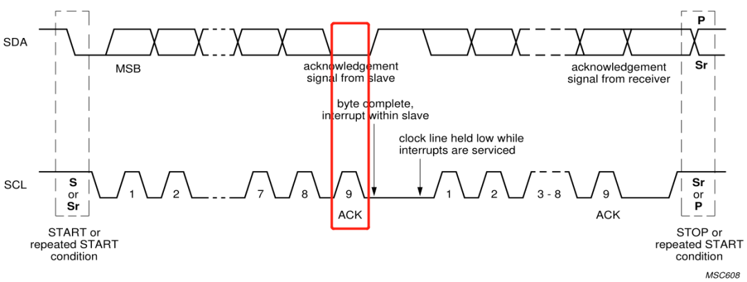
After the master sends 8 bits of data, it waits for an acknowledgment from the slave. In the 9th clock cycle, if the slave sends an acknowledgment, SDA will be pulled low.
(3) Non-Acknowledgment Signal
Similarly, in the 9th clock cycle, if there is no ACK, SDA will be set high.
4.2. Data Validity
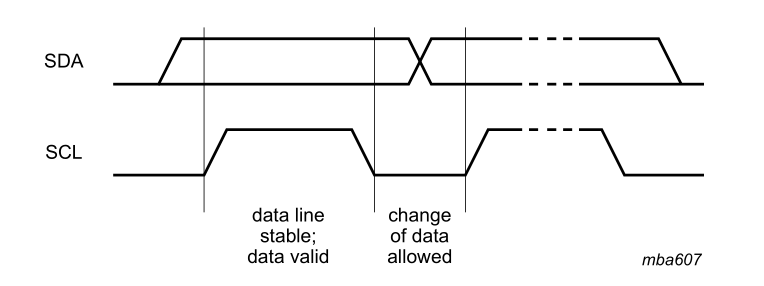
Data sampling in the I2C protocol occurs during the high state of SCL. Except for start and stop signals, during data transmission, SDA must remain stable while SCL is high, and can only change when SCL is low.
4.3. Write Timing
Timing for writing specified data to a designated register address:
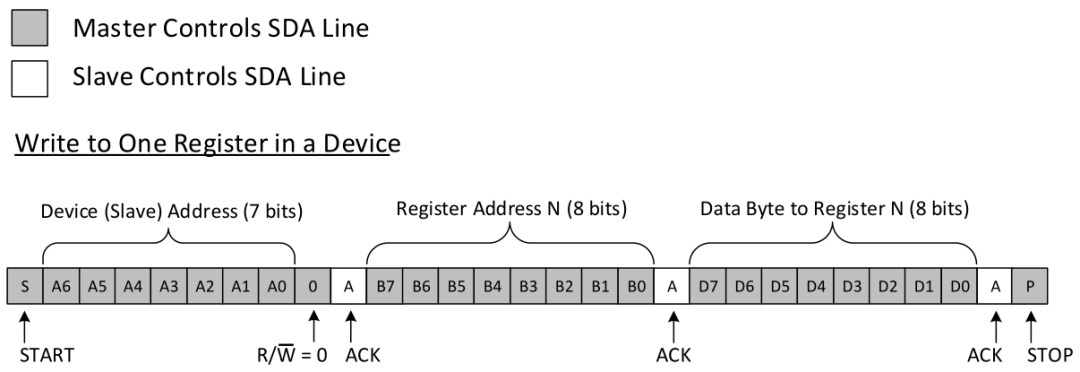
(1) Master sends start signal
(2) Sends slave address and write flag (‘0’)
(3) Slave sends ACK signal (acknowledgment)
(4) Master sends the register address to write after receiving the acknowledgment
(5) Slave sends ACK signal (acknowledgment)
(6) Master sends the value to write after receiving the acknowledgment
(7) Slave sends ACK signal (acknowledgment)
(8) Master sends stop signal
4.4. Read Timing
Timing for reading data from a specified register address:
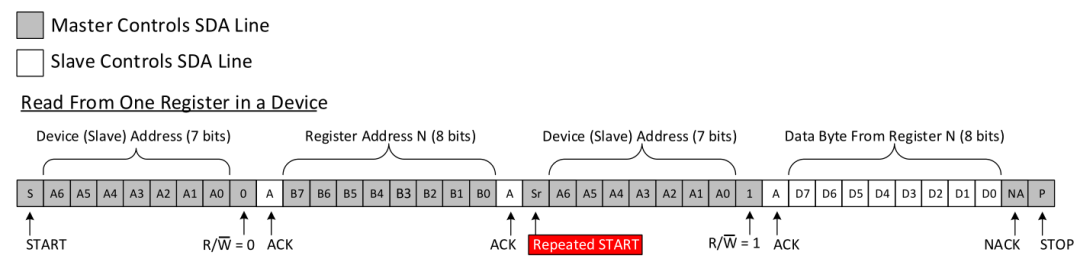
(1) Master sends start signal
(2) Sends slave address and write flag (‘0’)
(3) Slave sends ACK signal (acknowledgment)
(4) Master sends the register address to read after receiving the acknowledgment
(5) Slave sends ACK signal (acknowledgment)
(6) Master re-sends start signal
(7) Sends slave address and read flag (‘1’)
(8) Slave sends ACK signal (acknowledgment)
(9) Slave sends the value of the register
(10) Master sends NACK signal
(11) Master sends stop signal
END
Previous Articles
RECOMMEND
Recommendations
· Debugfs in Virtual File System
· Sysfs in Virtual File System
· Why does your /proc file always have errors? Try seq_file!
· Procfs in Virtual File System