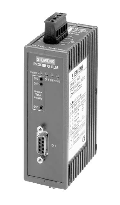
[Introduction] PROFIBUS fieldbus mostly uses RS485 for serial communication, but in some cases, it can also convert the cable into optical fiber for communication, and OLM is such a device.
 Technical communication, click here to join the group
 Sales procurement, click here to join the group
 Project docking, click here to join the group
 Talent recruitment, click here to join the group
OLM is very convenient to use, requiring no additional settings; in most cases, it can be used directly in its default state. However, users often feel confused about the DIP switch settings on the OLM and do not know how to set them. Here is a brief introduction. For detailed content, please refer to the relevant manual, where only the key parts are explained.
Talent recruitment, click here to join the group
OLM is very convenient to use, requiring no additional settings; in most cases, it can be used directly in its default state. However, users often feel confused about the DIP switch settings on the OLM and do not know how to set them. Here is a brief introduction. For detailed content, please refer to the relevant manual, where only the key parts are explained.
[1] Function IntroductionThe function settings of OLM are all done through the DIP switches on the template. There are some instructions on the side of the OLM to help users with the settings.
1.1 RS 485 Network Segment Monitoring (Segment monitoring at the RS 485 port)This function is used for each receiving device to monitor the fault frames or network congestion in the connected RS485 network segment. When the receiving device receives a fault frame or the network congestion lasts longer than the maximum frame transmission time, or if no signal is received for more than one second, the received signal will be “Blocked” and will no longer be forwarded to other ports until a new message can be received in the network. If this RS485 network segment does not activate this function, interference from the electrical network will affect the entire network.The following functions are limited to optical fiber.
1.2 Optical Path Monitoring (Line monitoring with echoes)The template has three functions for monitoring the optical path: “Send echo”, “Monitor echo” and “Suppress echo”.
Send echoMessages received through any port will be forwarded to all other ports. If the receiving port is an optical fiber interface, the receiving port will send back the message to the corresponding sending port.
Monitor echoWhen a template sends a message (not an “echo” message) to an optical fiber port, the optical fiber port expects to receive a response (“echo”). If no response message is received within a certain period (the time period is preset), an “echo” monitoring fault will occur, and the red fault light will illuminate.
Suppress echoWhen a data message is sent, the receiving device will be isolated from other ports until the response message (“echo”) is correctly received.
SegmentationIf an “echo” monitoring fault occurs on the optical fiber interface or a problematic message is detected, the template will assume that there is a problem with the line and will freeze this port from sending/receiving user data. The connected bus part will be separated from the entire network. At the same time, this separation will also cause the other end of the connected optical fiber to be separated.
All templates connected to the separated network segment will send test messages to these isolated ports. These test messages can be used to test the status of these bus segments. If all templates confirm through the test messages that the network segment no longer has issues, the segmentation status of that segment will be automatically canceled. If all components are “frozen”, the segmentation status of the template will automatically rotate to test its connection to the optical path of the adjacent template’s status. If no message blockage occurs and the network connection is normal, the corresponding port’s yellow light will flash periodically.
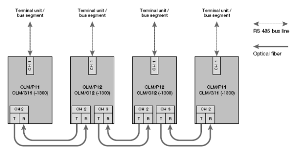
[2] Topology Structure
The topology structure of OLM generally includes the following types:
· Point-to-point connection
· Redundant optical fiber ring network
For connection principles in various topology structures, please refer to the manual. For example, when using optical fiber connections, the corresponding optical fiber port settings must be the same, and different models of OLM cannot be connected with optical fiber, etc.
The monitoring functions of the linear topology structure include:
When the monitoring mode is selected, the templates connected at both ends of the optical fiber will simultaneously monitor that connection. Once a fault is detected, the connection will be interrupted, and the PROFIBUS network will be split into two segments, with the fault indicator light turning on until the network is monitored to recover to normal through test messages.
Note: If there are multiple active sites (master stations) in the network, two logical token rings may form in the network. Each time two segments are combined into one segment, there may be a possibility of double tokens or message conflicts. Additionally, when a dual-port OLM template is used at the end of a linear network, the optical fiber port that is not connected to the network segment must not be set to “monitor” function, and it is best not to remove protective components to ensure that the port is not covered by dust.
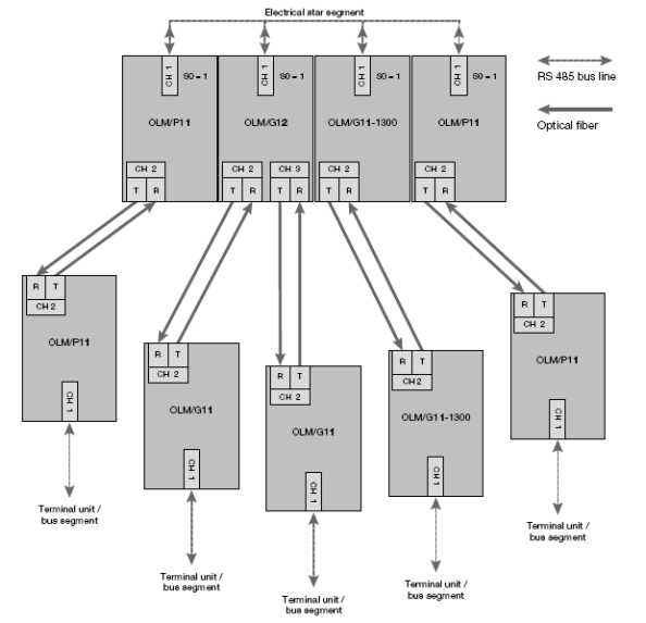
In the star topology structure, different models of OLM can be mixed. Please note: In the star network, all templates’ CH1 must be set to “Monitor off” (S0=1), so that the RS485 port will not be split by the network to ensure maximum availability of the star network. Unused optical fiber ports should also not be set to monitoring functions.The connections of network cables should be very secure to prevent interference from entering the entire network.All electrical network terminals in the star network should pay attention to set terminal resistors. As the electrical network segment of the star backbone (Electrical star segment), do not connect network devices.
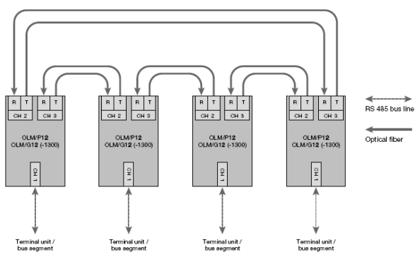
2.3 Redundant Ring Network
Figure4 Optical Fiber Redundant Ring Network
This topology structure is actually a special form of linear network topology. The “closed” optical cable ensures a high level of security for the network. The redundant optical fiber ring network must use dual optical fiber ports and must be of the same model of OLM.
The monitoring functions of the redundant ring network include:
The interruption of the ring network optical fiber will cause the ring network to be converted into a linear network. If there is a fault with the OLM template, the devices connected to that template will be separated from the network, and other network devices will become linear connections. At the same time, the red fault indicator light will illuminate. When the fault disappears, the network will automatically recover to a ring redundant structure.
Using a redundant ring network should meet the following conditions:
· All OLM models must be consistent.
· All OLM must set “Redundant optical ring”.
· All OLM must be connected through optical fiber ports, and there cannot be RS485 ports.
· Profibus network parameters MIN TSDR must be >=11. During network configuration, the station address should be set as low as possible to minimize the number of times the master station experiences a “Timeout” due to fault states.
· When a fault occurs in the redundant network (e.g., line disconnection), there will be a switching time during which data may not be transmitted normally. Therefore, it is recommended to set the repeat count of the master station message (Retry) to at least 3 times. Also, when the network recovers to a ring network, there will be no additional message indicating that the network has returned to normal. Even when the master station accesses a device address that does not exist, the master station will periodically attempt to address that device and wait for its response until the set “slot time” times out (“GAP request”), OLM accepts this state and restores the linear network to a redundant ring network.
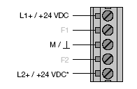
Configuration also needs attention:-The highest station address (HSA) is a range of addresses, and the allocation of station addresses should be between 0 and HAS, and do not allocate 0 and HSA to a specific station, and ensure the “gap” address interval; otherwise, when the fault disappears, the network cannot automatically close, and the fault indicator light and fault signal contact coil (Figure 5) will not reset.
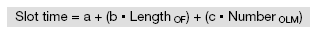
The method of using this coil can be found in the manual; it will not be detailed here. The “slot time” setting should be close to twice that of a non-redundant network structure, as detailed in the calculation formula below.
Where:“Slot time” represents the monitoring “bit” time; “Length OF” is the total length of all optical fibers (segmented network) in kilometers; “Number OLM” is the number of all OLM in the network.
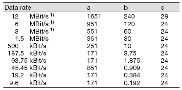
a, b and c should be chosen according to the baud rates in the table:
Table 1a Redundant Ring Network DP standard Protocol CalculationSlot time Parameters
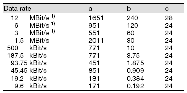
Table 1b Redundant Ring Network DP/FMS (universal) Protocol CalculationSlot time Parameters
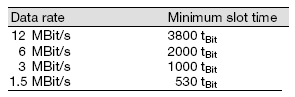
The above table notes 1):Using OLM/G11-1300 and OLM/G12-1300 when the baud rate is 12 MBit/s, 6 MBit/s, 3 MBit/s and 1.5 MBit/s, the minimum “slot time” should be set according to the table below.
Table 2 Minimum slot time Setting
In this calculation formula, all parameters are for the optical fiber network. In this formula, it is assumed that the maximum length of the bus segment on the OLM via RS485 is 20m. If this distance is exceeded, the excess part should be added to the optical fiber length parameter (Length OF) for calculation. Of course, the RS485 network segment can exceed 20m, but the excess part must be included in the calculation. If the slot time is too small, the OLM system indicator light will alarm: red/green flashing alternately.
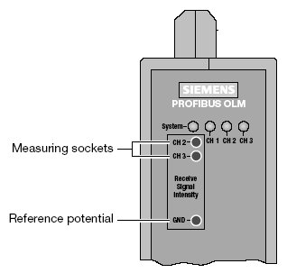
[3] Detection of Optical Fiber Receiving Port Signals
Figure6 Optical Fiber Port Voltage Detection Socket
The signal strength of the two optical fiber channels CH2/CH3 can be measured with a voltmeter, and their signal strength conforms to the following diagram.
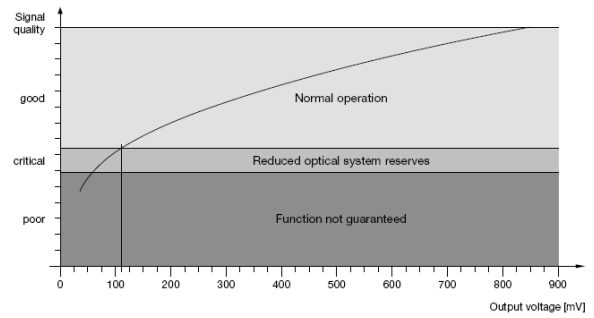
Figure7 The relationship between the optical fiber port signal strength and detection voltage
If the optical fiber is disconnected at the receiving port, the detection voltage will drop from the normal range to an abnormal range (for example, from 600mV to below 100mV or even to 0mV), but this only detects the signal at the receiving port; if the sending port is disconnected, this method cannot detect it.
 [Video] How German Engineers Make PLC Cabinets?
 [Video] How are German WITRON Electrical Cabinets Produced?
 [Video] What is the Office Environment of German Engineers Like?
 [Video] Why is PROFINET Better than PROFIBUS?
 Reply “1200yd” to download motion control examples