Introduction to Serial Communication
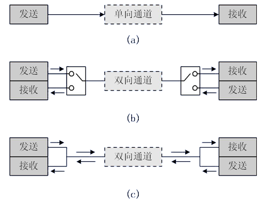
Classification Based on Data Transmission Direction
-
Simplex: Data transmission only supports data transfer in one direction.
-
Half-Duplex: Allows data to be transmitted in both directions. However, at any given time, data can only be transmitted in one direction, which is essentially a switched direction simplex communication; it does not require separate receiving and transmitting ends, as both can use the same port.
-
Full-Duplex: Allows data to be transmitted simultaneously in both directions. Therefore, full-duplex communication is a combination of two simplex communication methods and requires independent receiving and transmitting ends.
As shown in the figures below: a, b, c.
Classification Based on Communication Method
-
Synchronous Communication: Transmission with clock synchronization signals. For example: SPI, IIC communication interfaces.
-
Asynchronous Communication: Without clock synchronization signals. For example: UART (Universal Asynchronous Receiver-Transmitter), single bus.
In synchronous communication, a signal line is used to transmit signals above the transmitting and receiving devices, coordinating data synchronously under the drive of the clock signal. For instance, both parties usually agree to sample the data line at the rising or falling edge of the clock signal during communication.
In asynchronous communication, clock signals are not used for data synchronization; instead, they directly intersperse some synchronization signal bits within the data signal or package the subject data for transmission in data frame format. During communication, both parties must agree on the data transmission rate (baud rate) to better synchronize. Common baud rates include 4800bps, 9600bps, 115200bps, etc.
In synchronous communication, most of the content transmitted by the data signal is valid data, while asynchronous communication includes various identifiers of the data frame. Thus, synchronous communication is more efficient, but the clocks of both parties in synchronous communication allow for little error; a slight clock error can lead to data corruption, while asynchronous communication allows for larger clock errors.
Basics of STM32 Serial Communication
STM32 has two types of serial communication interfaces: UART (Universal Asynchronous Receiver-Transmitter) and USART (Universal Synchronous/Asynchronous Receiver-Transmitter). For the large-capacity STM32F10x series chips, there are 3 USART and 2 UART.
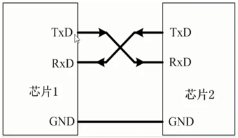
UART Pin Connection Method
-
RXD: Data input pin, for data reception.
-
TXD: Data output pin, for data transmission.
For the connection between two chips, both chips share a common ground (GND), and TXD and RXD are cross-connected. Here, the cross-connection means that Chip 1’s RXD connects to Chip 2’s TXD, and Chip 2’s RXD connects to Chip 1’s TXD. This way, the two chips can communicate at TTL levels.
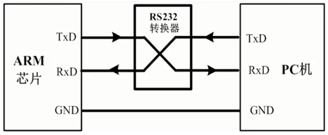
If the chip is connected to a PC (or host), besides sharing a common ground, direct cross-connection cannot be used. Although both the PC and the chip have TXD and RXD pins, the PC (or host) usually uses an RS232 interface (commonly a DB9 package), thus direct cross-connection is not possible. The RS232 interface has 9 pins, where TXD and RXD are usually obtained through level conversion. Therefore, to enable direct communication between the chip and the PC’s RS232 interface, the chip’s input and output ports must also be level-converted to RS232 type before cross-connection.
After level conversion, the voltage standards of the chip’s serial port and RS232 are different:
-
The microcontroller uses TTL levels: +5V represents 1, 0V represents 0.
-
RS232 uses negative logic levels, -3~-15V for 1, +3~+15V for 0.
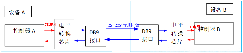
The communication structure diagram between devices using the RS-232 communication protocol standard is as follows:
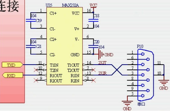
Therefore, the communication between the microcontroller’s serial port and the PC’s serial port should follow the connection method below: between the microcontroller’s serial port and the RS232 port provided by the host, a level conversion circuit (such as the Max232 chip shown in the figure below) is used to achieve conversion between TTL levels and RS232 levels. The P10 in the figure below refers to the DB9 mentioned earlier.
-
Full-duplex asynchronous communication;
-
Fractional baud rate generator system, providing precise baud rates. The shared programmable baud rate for sending and receiving can reach up to 4.5Mbits/s;
-
Programmable data word length (8 bits or 9 bits);
-
Configurable stop bits (supporting 1 or 2 stop bits);
-
Configurable DMA multi-buffer communication;
-
Separate transmitter and receiver enable bits;
-
Detection flags: ① Receive buffer ② Transmit buffer empty ③ Transmission complete flag;
-
Multiple interrupt sources with flags, triggering interrupts;
-
Others: Parity control, four error detection flags.
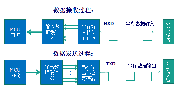
Serial Communication Process
The data packets in serial communication are transmitted from the sending device through its TXD interface to the receiving device’s RXD interface. The data packet formats of both parties must be consistent to send and receive data normally. The parameters that need to be defined for asynchronous communication in STM32 include: start bit, data bits (8 bits or 9 bits), parity bit (9th bit), stop bits (1, 1.5, or 2 bits), and baud rate settings.
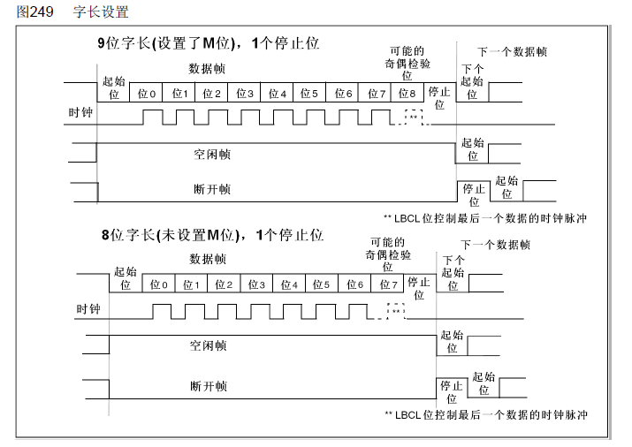
UART serial communication data packets are structured in frames, with a commonly used frame structure being: 1 start bit + 8 data bits + 1 parity bit (optional) + 1 stop bit. As shown in the figure below:
The parity bit can be odd or even, which is a simple method for error checking. Odd parity means that the total number of 1s in the 9 bits (data bits and parity bit) must be odd; even parity means that the total number of 1s must be even.
Besides odd (odd) and even (even) parity, there can also be: 0 parity (space), 1 parity (mark), and no parity (noparity). 0/1 parity means that regardless of the content of valid data, the parity bit is always 0 or 1.
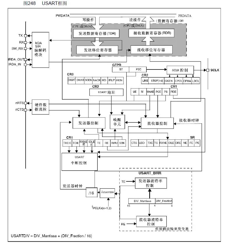
This block diagram is divided into three parts: upper, middle, and lower parts, which can be found in the description in the “STM32 Chinese Reference Manual”.
In the upper part of the block diagram, data enters the receive shift register from RX, then goes to the receive data register, which is finally read by the CPU or DMA; data from the CPU or DMA is passed to the transmit data register, then enters the transmit shift register, and is sent out through TX.
However, both sending and receiving in UART require baud rate control. How is the baud rate controlled?
This leads us to the lower part of the block diagram, where there are arrows entering the receive shift register and transmit shift register, connecting to the receiver control and transmitter control, respectively. This means that although asynchronous communication does not have clock synchronization signals, there are clock signals provided internally in the serial port for control. The receiver clock and transmitter clock are controlled by the same control unit, which means they share a baud rate generator. It can also be seen how to calculate the receiver clock (generator clock) and USRRTDIV.
Here is a knowledge point to note:
-
UART1 clock: PCLK2 (high speed)
-
UART2, UART3, UART4 clock: PCLK1 (low speed)
Copyright belongs to the original author. If there is any infringement, please contact for deletion.
Full-stack engineer? You can’t extract gold, how can you!
The boss is coming | How to use Alibaba Cloud IoT HaaS development board to make a remote AI face recognition monitoring project?
10 Tips for Embedded Software Testing