Click the blue text above: IoT Inn to follow us.
In previous sections, we used the LED light, buzzer, and relay components, driven by the GPIO output function of STM32. In this section, we will learn about the GPIO input function. When an external button is pressed, the microcontroller can detect it in real-time. Buttons are common input devices in embedded system development. Generally, buttons can set system parameters and control system operation states.
1Introduction to STM32 IoT Kit
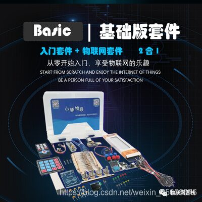
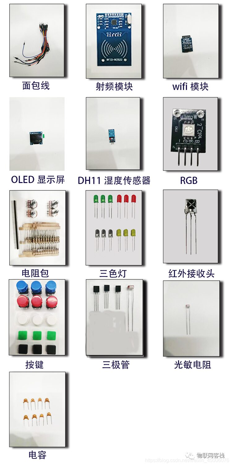
The STM32 IoT Kit currently has two versions: Basic and Advanced. Future versions will include application and voice versions. The core board uses the STM32F103C8T6 core board, and the main components of the basic version are shown below:
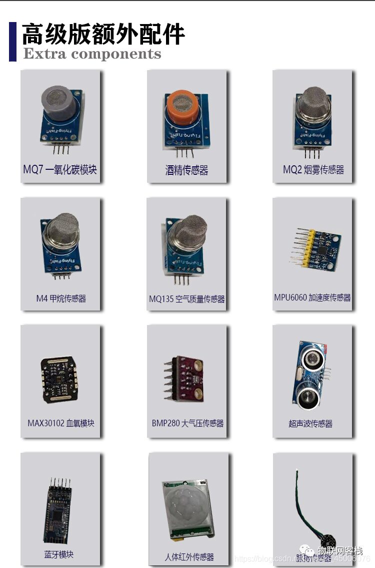
The main components of the advanced version are shown below:
The STM32 IoT Kit aims to help everyone get started with the Internet of Things (IoT). Not only do you learn about STM32, but you also understand development of WeChat Mini Programs and IoT server backends, truly comprehending all aspects of an IoT project. Based on this, we have customized a universal WIFI communication protocol (which can be understood as similar to AT commands, but with higher integration; just a few commands can connect directly to the cloud platform), such as three commands to connect to Tencent Cloud instances.
We will continue to add support for mainstream cloud platforms such as Tuya Smart, Telecom Cloud, Mobile Onenet, and Alibaba Cloud, striving to allow a single STM32 code to connect to different cloud platforms through customized WIFI modules. We also welcome friends with product development needs to privately message us for consultation and customization of IoT solutions!
This IoT kit can support college students participating in IoT-related competitions, applying for school innovation projects, completing graduation designs, etc. Our positioning is to be an open-source smart hardware service provider, exploring the IoT together with everyone. Our mission is to promote the landing and popularization of more IoT products, making technology no longer a barrier!
2 Introduction to Buttons
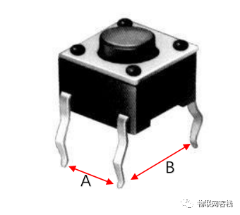
Common buttons use mechanical elastic switches. When the mechanical contacts open or close, the voltage signal changes. The common button switches are shown below, where the A terminal pin is on the same side and defaults to open, while the B terminal pin is on the opposite side and defaults to closed. When the button is pressed, A connects, and B disconnects.
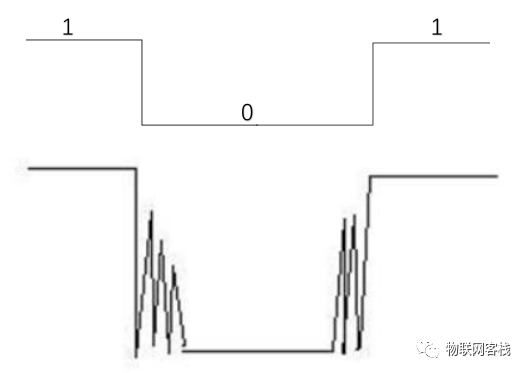
Such switches typically do not connect immediately when pressed; the transition between on and off is accompanied by a series of jitters, generally lasting from 5ms to 10ms. The specific jitter time is determined by the mechanical characteristics of the button, as shown in the figure below:
To solve this problem, hardware debouncing and software debouncing can be used. The principle of hardware debouncing is to use a capacitor to smooth the signal, and then after shaping with a Schmitt inverter, a clean pulse wave without glitches is obtained. In most practical projects, to save costs, software filtering is usually adopted. Software filtering generally uses a delay method. When the button is first detected as pressed, the software waits for about 10ms and then checks the button state again. If it is still pressed, it is considered that the button is pressed.
3Principle of Button Detection
The simple circuit schematic of an independent button connection is shown below:
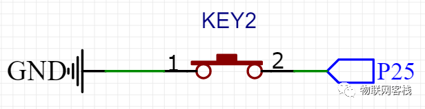
In the independent button circuit, one side of the button is connected to GND, and the other side is connected to the microcontroller’s IO port. When the button is pressed, the two sides 1 and 2 connect, and the microcontroller’s P2.5 pin is directly connected to GND, resulting in a low level. Therefore, the microcontroller only needs to continuously check whether the P2.5 pin’s I/O port is low. Once the program detects that the I/O port pin is low, it indicates that the button is pressed.
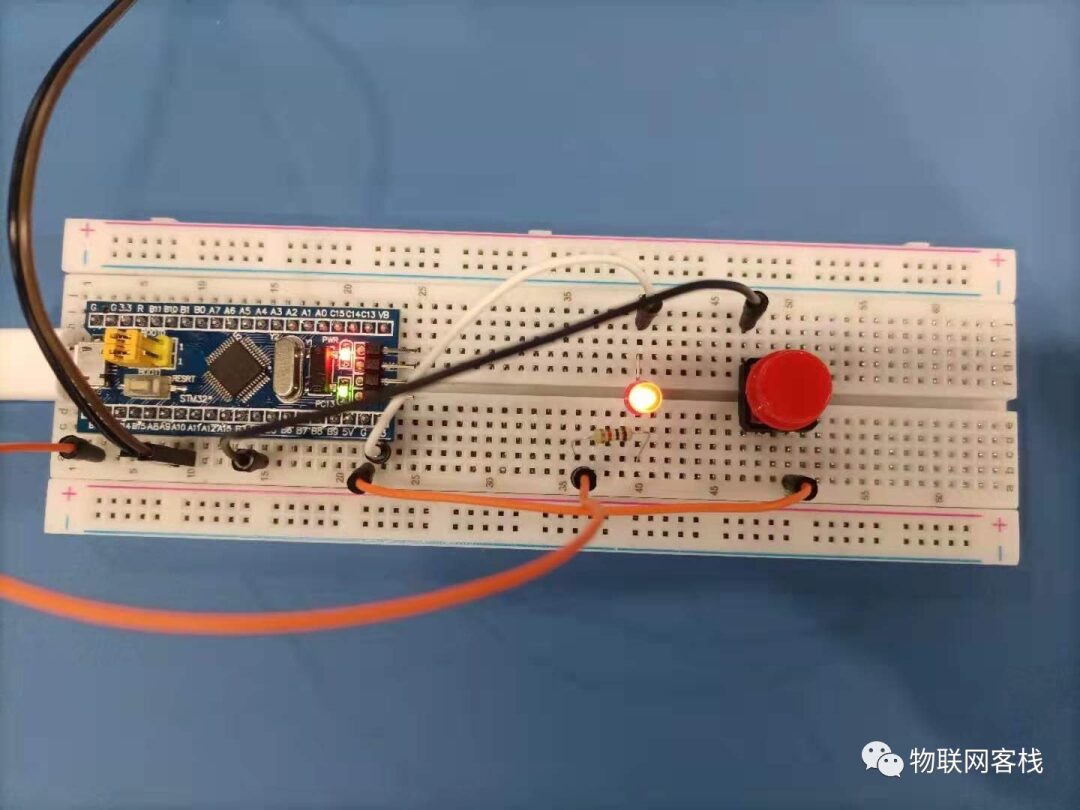
4Hardware Design
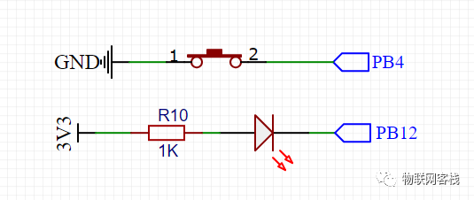
The schematic diagram of the button part for this button experiment is shown below. One side of the button pins is grounded, and the other side is connected to the microcontroller PB4. When the button is pressed, PB4 is low.
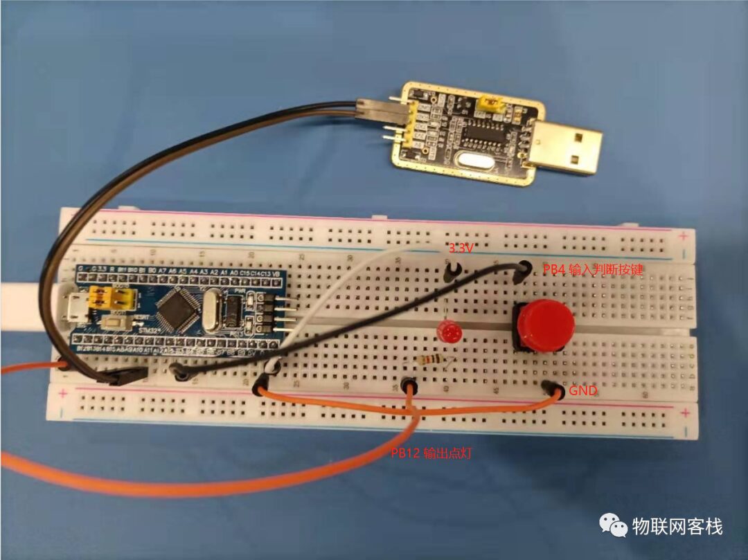
The physical diagram is shown below:
Here, the PB12 pin outputs a low level to light the LED. When the button is pressed, the microcontroller detects that the PB4 pin is low, and then lights up the LED.
1Create a New Project
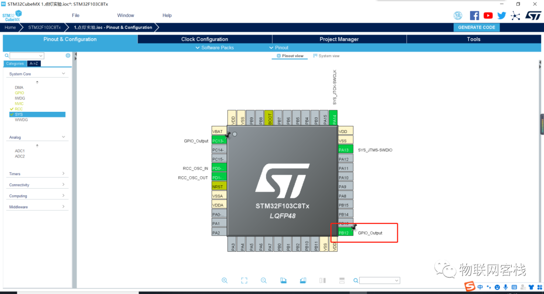
Use STM32CubeMX to create a new project, refer to the environment setup chapter for configuration methods, and set RCC and PB12 pin output.
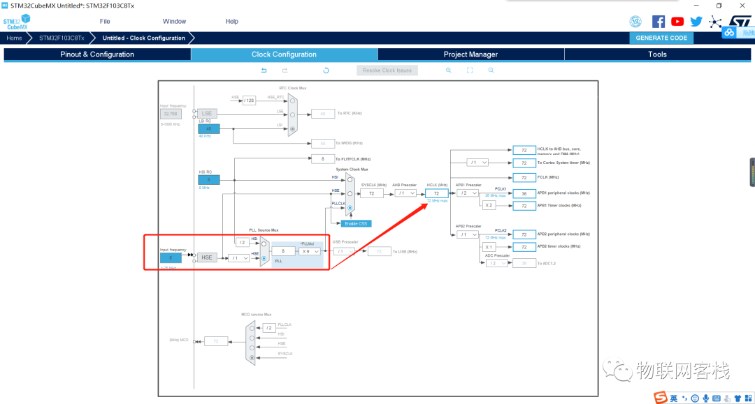
Enter the Clock configuration page, select HSE clock source, and after frequency doubling, the main clock is 72MHz.
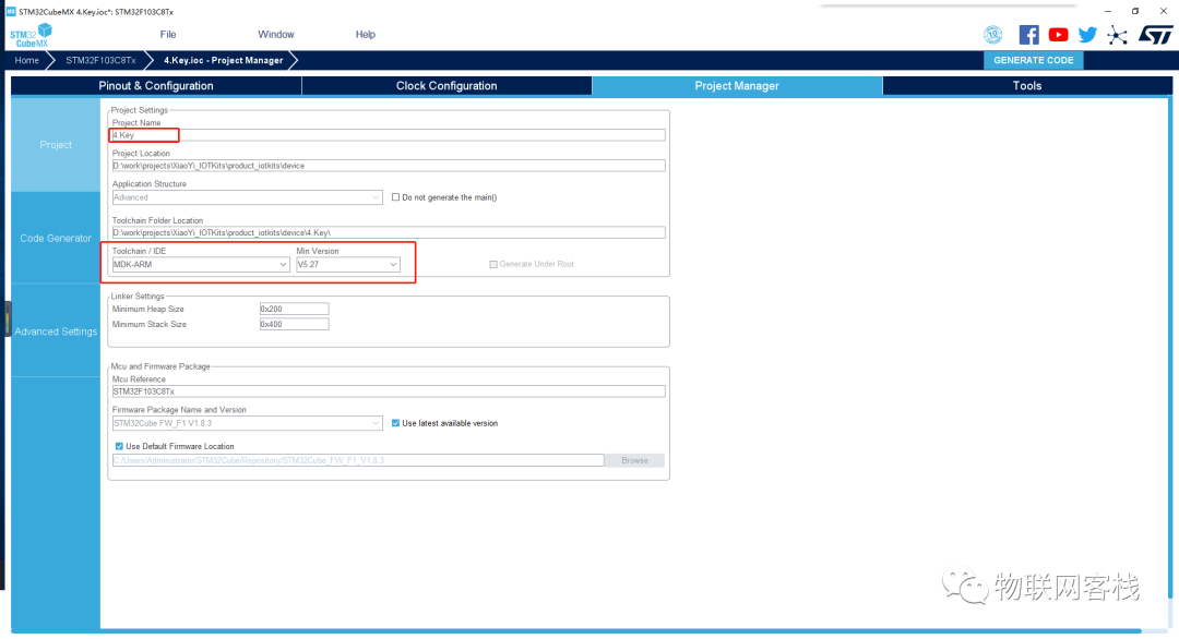
Switch to the Project Manager section, set the project name, project save directory, toolchain, and other information as shown below:
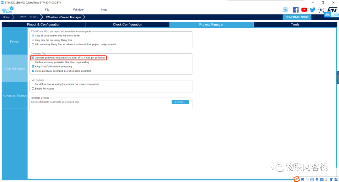
Click the Code Generator on the left, then check Generate peripheral initialization as a pair of ‘.c/.h’ files per peripheral. By checking this option, peripherals will be saved in a separate file instead of all in main.c.
Then open the MDK-ARM/4.Key.uvprojx project.
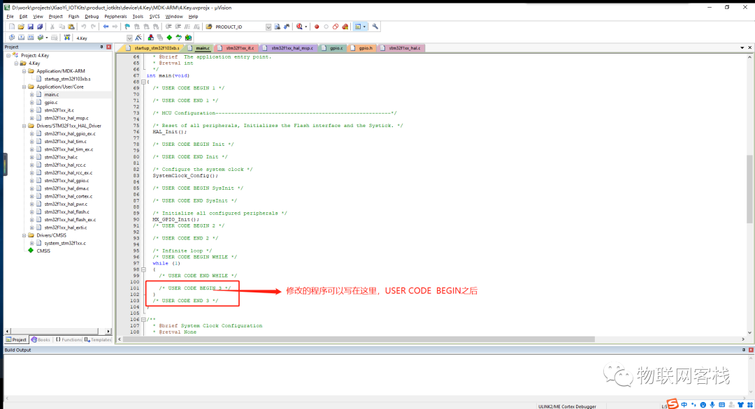
2Modify the Program
First, we write the button detection function so that the system can detect it in real-time when the button is pressed. Note that the program uses a 20ms delay for debouncing to prevent abnormal triggering of the button.
int key_scan(void){ if (0 == HAL_GPIO_ReadPin(GPIOB, GPIO_PIN_4)) { HAL_Delay(20); if (0 == HAL_GPIO_ReadPin(GPIOB, GPIO_PIN_4)) { return 1; } } return 0;}Then we start writing the main function control logic to implement the effect of turning the LED on and off when the button is pressed.
/** * @brief The application entry point. * @retval int */ int main(void) { /* USER CODE BEGIN 1 */ int flag_led = 0; /* USER CODE END 1 */ /* MCU Configuration--------------------------------------------------------*/ /* Reset of all peripherals, Initializes the Flash interface and the Systick. */ HAL_Init(); /* USER CODE BEGIN Init */ /* USER CODE END Init */ /* Configure the system clock */ SystemClock_Config(); /* USER CODE BEGIN SysInit */ /* USER CODE END SysInit */ /* Initialize all configured peripherals */ MX_GPIO_Init(); /* USER CODE BEGIN 2 */ /* USER CODE END 2 */ /* Infinite loop */ /* USER CODE BEGIN WHILE */ while (1) { /* USER CODE END WHILE */ /* USER CODE BEGIN 3 */ if ( key_scan() ) { if ( flag_led ) { HAL_GPIO_WritePin(GPIOB, GPIO_PIN_12, GPIO_PIN_RESET); } else { HAL_GPIO_WritePin(GPIOB, GPIO_PIN_12, GPIO_PIN_SET); } // Toggle flag_led to achieve LED on/off effect flag_led = !flag_led; } HAL_Delay(10); } /* USER CODE END 3 */ }Download the program to the core board according to the environment setup chapter. You can see that pressing the button controls the LED light.
If you have any questions during use, please join our QQ group for further communication.
QQ group: 906015840 (Note: IoT project communication)
Source code acquisition: Follow the public account and reply xiaoyi_stm32kits to obtain materials.
Hardware acquisition: Search for Xiaoyi IoT on a certain treasure.
Acquire hardware through the mini program.
Xiaoyi IoT produces: A grain of sand, a world; a leaf, a Bodhi.