
Software and Hardware Integration
Address Space
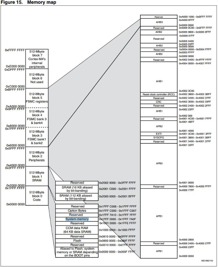
We all know that our computers have 32-bit and 64-bit systems. Why? Because in a 32-bit system, the PC pointer is a 32-bit binary number, which is 0xffffffff, and the range is only 4G of addressing space. As memory becomes larger, 4G is simply not enough, so it needs to be expanded. To access memory beyond 4G, a 64-bit system was created. How many bits is the STM32? It is 32-bit, hence the PC pointer is also 32-bit, and the addressing space is 4G.
-
On the far left, there are 8 blocks, each 512M, totaling 4G, which is the chip’s addressing space.
-
Block 0 contains a section called FLASH, which is the internal FLASH where our program is downloaded, starting at address 0X8000000. Note that this only has 1M of space. Now STM32 has chips with 2M flash; where does the FLASH beyond 1M go? Please refer to the corresponding chip manual.
-
In block 1, there are two segments of SRAM, totaling 128K, which is the memory we mentioned earlier, used to store variables used by the program. If needed, the program can also run from SRAM. Doesn’t the 407 have 196K?
-
Actually, the 407 has 196K of memory, but 64K is not ordinary SRAM; it is located in block 0’s CCM. These two areas are not contiguous, and CCM can only be used by the core; peripherals cannot use CCM memory, or else it will crash.
-
Block 2 is for Peripherals, which is the peripheral space. Looking to the right, it mainly involves APB1/APB2, AHB1/AHB2; what are these? We will discuss this later.
-
Blocks 3, 4, and 5 are for FSMC space, which can expand to external SRAM, NAND FLASH, LCD, and other peripherals.
GPIO_SetBits(GPIOG, GPIO_Pin_0 | GPIO_Pin_1 | GPIO_Pin_2 | GPIO_Pin_3);void GPIO_SetBits(GPIO_TypeDef* GPIOx, uint16_t GPIO_Pin){ /* Check the parameters */ assert_param(IS_GPIO_ALL_PERIPH(GPIOx)); assert_param(IS_GPIO_PIN(GPIO_Pin)); GPIOx->BSRRL = GPIO_Pin;}assert_param: This is an assertion used to check whether the input parameters meet the requirements. GPIOx is an input parameter, which is a pointer to a GPIO_TypeDef structure, so we use -> to access its members.
#define GPIOG ((GPIO_TypeDef *) GPIOG_BASE)#define GPIOG_BASE (AHB1PERIPH_BASE + 0x1800)/*!< Peripheral memory map */#define APB1PERIPH_BASE PERIPH_BASE#define APB2PERIPH_BASE (PERIPH_BASE + 0x00010000)#define AHB1PERIPH_BASE (PERIPH_BASE + 0x00020000)#define AHB2PERIPH_BASE (PERIPH_BASE + 0x10000000)#define PERIPH_BASE ((uint32_t)0x40000000)u32 i; i = 0x55aa55aa;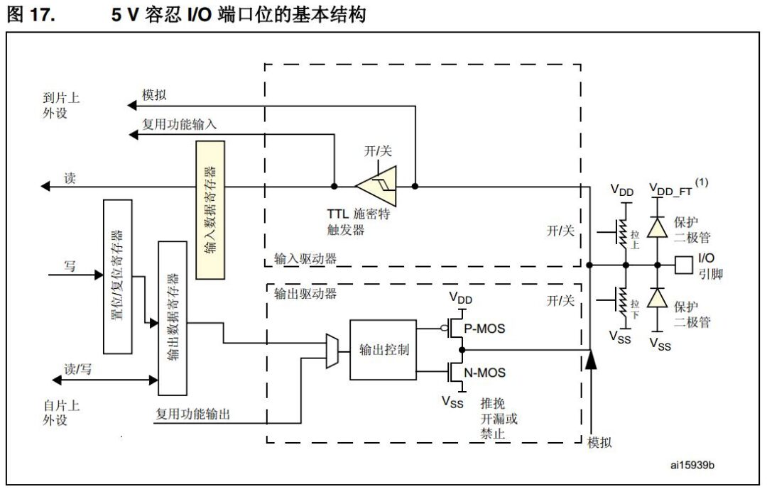
Registers should actually be considered a general term for memory; peripheral registers should be called special registers. Gradually, everyone started referring to peripherals as registers, while others are referred to as memory or RAM. Why can registers control hardware peripherals? Because, roughly speaking, a BIT in a register is a switch: on is 1, off is 0. By using this electronic switch to control the circuit, we control the peripheral hardware.
Pure Software – A Comprehensive Small Program
Analyzing Startup Code
-
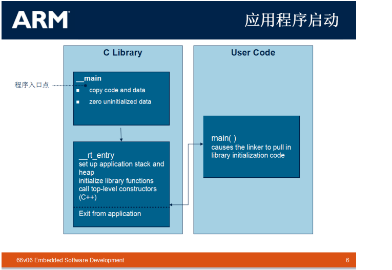
Where does the function start running?
; Vector Table Mapped to Address 0 at Reset AREA RESET, DATA, READONLY EXPORT __Vectors EXPORT __Vectors_End EXPORT __Vectors_Size__Vectors DCD __initial_sp ; Top of Stack DCD Reset_Handler ; Reset Handler DCD NMI_Handler ; NMI Handler DCD HardFault_Handler ; Hard Fault Handler DCD MemManage_Handler ; MPU Fault Handler DCD BusFault_Handler ; Bus Fault Handler DCD UsageFault_Handler ; Usage Fault Handler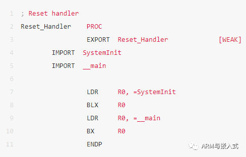
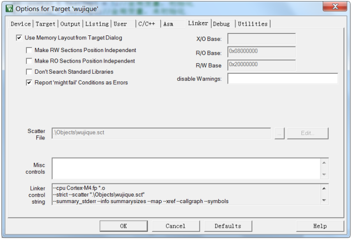
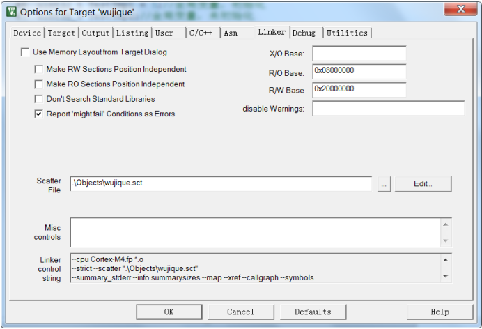
This file is actually very powerful; by modifying this file, many program features can be configured, such as: 1. Specifying FLASH and RAM sizes and starting positions. When we divide the program into BOOT, CORE, APP, or even perform driver separation, this can come in handy. 2. Specifying the locations of functions and variables, for example, loading functions to run in RAM.
-
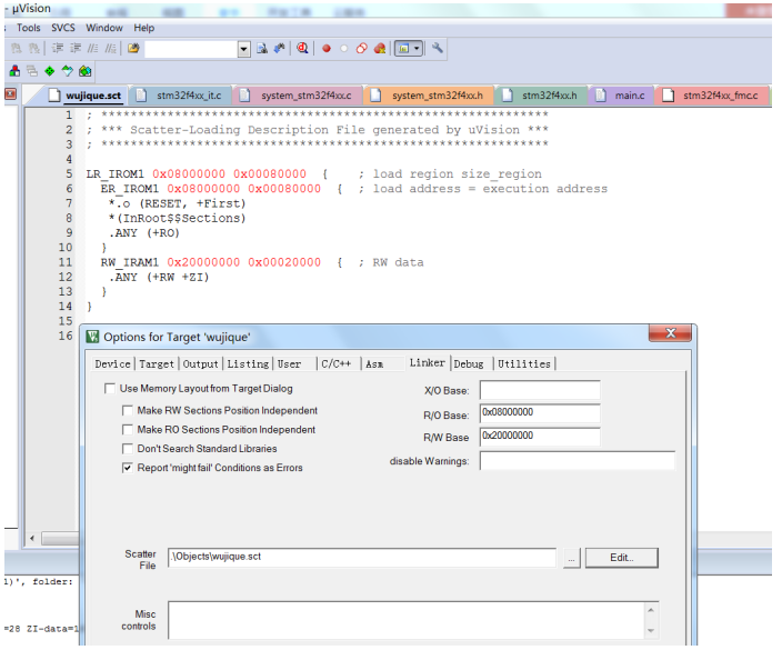
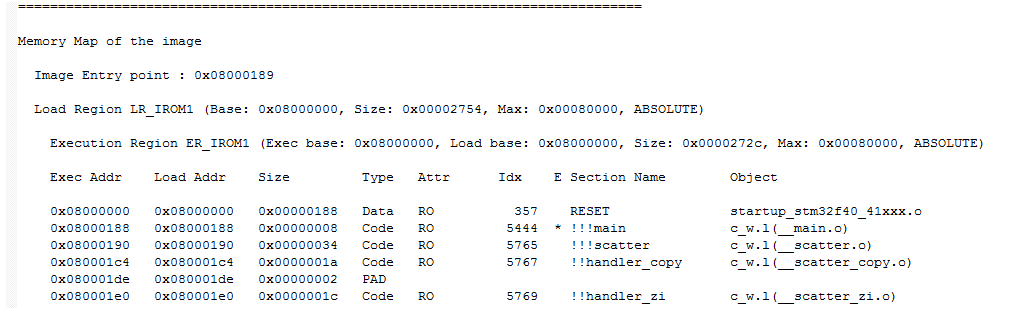
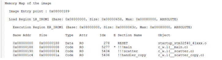
Line 6 ER_IROM1 0x08000000 0x00080000 defines ER_IROM1, which is our internal FLASH starting from 0x08000000 with a size of 0x00080000.
-
Line 7 .o (RESET, +First) starts from 0x08000000, first placing a .o file, and using (RESET, +First) to specify that the RESET block is prioritized for placement. What is the RESET block? Please check the startup code; the interrupt vector is an AREA named RESET, which belongs to READONLY. This means that after compilation, the RESET block will be placed at the 0x08000000 position, which means the interrupt vector will be placed here. DCD allocates space, 4 bytes, the first being __initial_sp, and the second being the pointer to the Reset_Handler function. This means that after compilation, the pointer (address) of the Reset_Handler function will be placed at 0x800000+4. Therefore, when the chip resets, it can find the reset function Reset_Handler.
-
Line 8 *(InRoot$$Sections) What is this? GOOGLE it! We will discuss it later.
-
Line 9 .ANY (+RO) means all other RO will be placed subsequently. This means other code will follow the startup code.
-
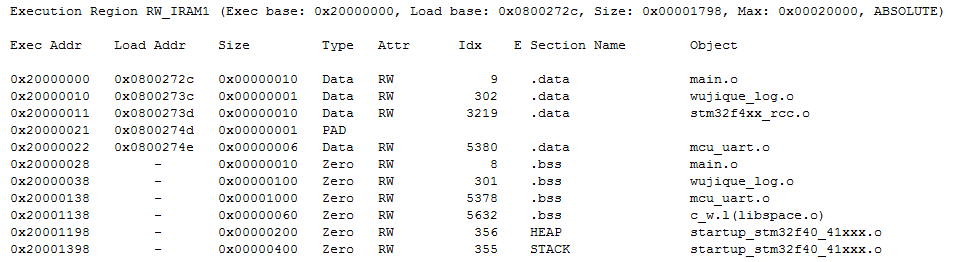
Line 11 RW_IRAM1 0x20000000 0x00020000 defines the size of RAM.
-
Line 12 .ANY (+RW +ZI) means all RW and ZI will be placed in RAM. RW, ZI refer to variables, this line specifies where variables will be stored.
Analyzing User Code
int main(void){ GPIO_InitTypeDef GPIO_InitStructure; /*!< At this stage the microcontroller clock setting is already configured, this is done through SystemInit() function which is called from startup files before to branch to application main. To reconfigure the default setting of SystemInit() function, refer to system_stm32f4xx.c file */ /* SysTick end of count event each 10ms */ RCC_GetClocksFreq(&RCC_Clocks); SysTick_Config(RCC_Clocks.HCLK_Frequency / 100); /* Add your application code here */ /* Insert 50 ms delay */ Delay(5);/* Initialize LED IO port */ RCC_AHB1PeriphClockCmd(RCC_AHB1Periph_GPIOG, ENABLE); GPIO_InitStructure.GPIO_Pin = GPIO_Pin_0 | GPIO_Pin_1 | GPIO_Pin_2 | GPIO_Pin_3; GPIO_InitStructure.GPIO_Mode = GPIO_Mode_OUT; GPIO_InitStructure.GPIO_OType = GPIO_OType_PP; GPIO_InitStructure.GPIO_Speed = GPIO_Speed_100MHz; GPIO_InitStructure.GPIO_PuPd = GPIO_PuPd_UP; GPIO_Init(GPIOG, &GPIO_InitStructure); /* Infinite loop */ mcu_uart_open(3); while (1){ GPIO_ResetBits(GPIOG, GPIO_Pin_0|GPIO_Pin_1|GPIO_Pin_2|GPIO_Pin_3); Delay(100); GPIO_SetBits(GPIOG, GPIO_Pin_0|GPIO_Pin_1|GPIO_Pin_2|GPIO_Pin_3); Delay(100); mcu_uart_test(); TestFun(TestTmp2);}/* Private functions ---------------------------------------------------------*/ u32 TestTmp1 = 5; // Global variable, initialized to 5 u32 TestTmp2; // Global variable, uninitialized const u32 TestTmp3[10] = {6,7,8,9,10,11,12,13,12,13}; u8 TestFun(u32 x) // Function with one parameter, returning a u8 value { u8 test_tmp1 = 4; // Local variable, initialized u8 test_tmp2; // Local variable, uninitialized static u8 test_tmp3 = 0; // Static local variable test_tmp3++; test_tmp2 = x; if(test_tmp2 > TestTmp1) test_tmp1 = 10; else test_tmp1 = 5; TestTmp2 += TestTmp3[test_tmp1]; return test_tmp1;}/** * @brief Inserts a delay time. * @param nTime: specifies the delay time length, in milliseconds. * @retval None */ void Delay(__IO uint32_t nTime){ uwTimingDelay = nTime; while(uwTimingDelay != 0);}/** * @brief Decrements the TimingDelay variable. * @param None * @retval None */ void TimingDelay_Decrement(void){ if (uwTimingDelay != 0x00) { uwTimingDelay--; }}/** * @brief This function handles SysTick Handler. * @param None * @retval None */ void SysTick_Handler(void){ TimingDelay_Decrement();}__Vectors DCD __initial_sp ; Top of Stack DCD Reset_Handler ; Reset Handler DCD NMI_Handler ; NMI Handler DCD HardFault_Handler ; Hard Fault Handler DCD MemManage_Handler ; MPU Fault Handler DCD BusFault_Handler ; Bus Fault Handler DCD UsageFault_Handler ; Usage Fault Handler DCD 0 ; Reserved DCD 0 ; Reserved DCD 0 ; Reserved DCD 0 ; Reserved DCD SVC_Handler ; SVCall Handler DCD DebugMon_Handler ; Debug Monitor Handler DCD 0 ; Reserved DCD PendSV_Handler ; PendSV Handler DCD SysTick_Handler ; SysTick HandlerRemaining Questions
Understanding Code Composition Through MAP Files
Compilation Results
*** Using Compiler 'V5.06 update 5 (build 528)', folder: 'C:\Keil_v5\ARM\ARMCC\Bin' Build target 'wujique' compiling stm32f4xx_it.c...... assembling startup_stm32f40_41xxx.s... compiling misc.c...... compiling mcu_uart.c... linking... Program Size: Code=9038 RO-data=990 RW-data=40 ZI-data=6000 FromELF: creating hex file...".\Objects\wujique.axf" - 0 Error(s), 0 Warning(s). Build Time Elapsed: 00:00:32
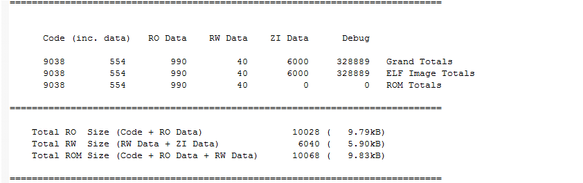
The build target is wujique. Compiling C files and assembling assembly files; this process is called compilation. After compilation, linking occurs. Finally, we obtain a compilation result: 9038 bytes of code, 990 RO, 40 RW, 6000 ZI. CODE is the code, which is easy to understand; what are RO, RW, and ZI? FromELF creates hex files; FromELF is a good tool that needs to be added to options to use.
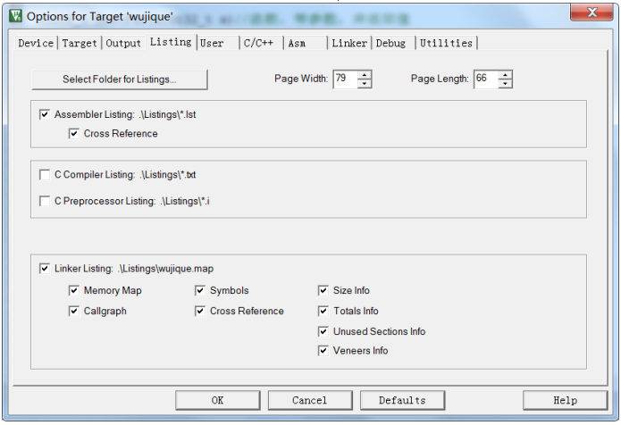
MAP File Configuration
The default settings may not check many compilation information boxes; checking all information will increase compilation time.
MAP File
-
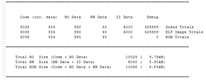
Total MAP Information
-
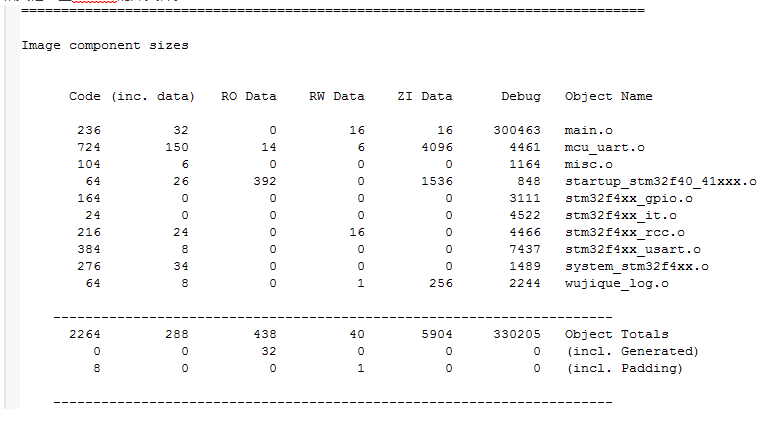
Image Component Sizes
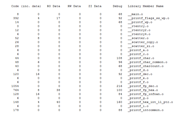
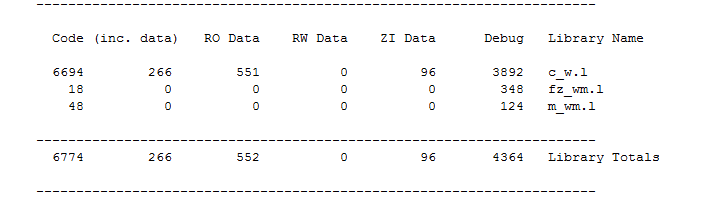
What are library files? Library files are pre-written code libraries. In code, we often include some header files, such as: #include <stdarg.h> #include <stdlib.h> #include <string.h>These are the header files of the library. These header files are stored in the installation directory of the MDK development tool. Commonly used library functions include: memcpy, memcmp, strcmp, etc. As long as these functions are included in the code, the library files will be linked.
-
MAP File
What are library files?
#include <stdarg.h> #include <stdlib.h> #include <string.h>-
MAP File
-
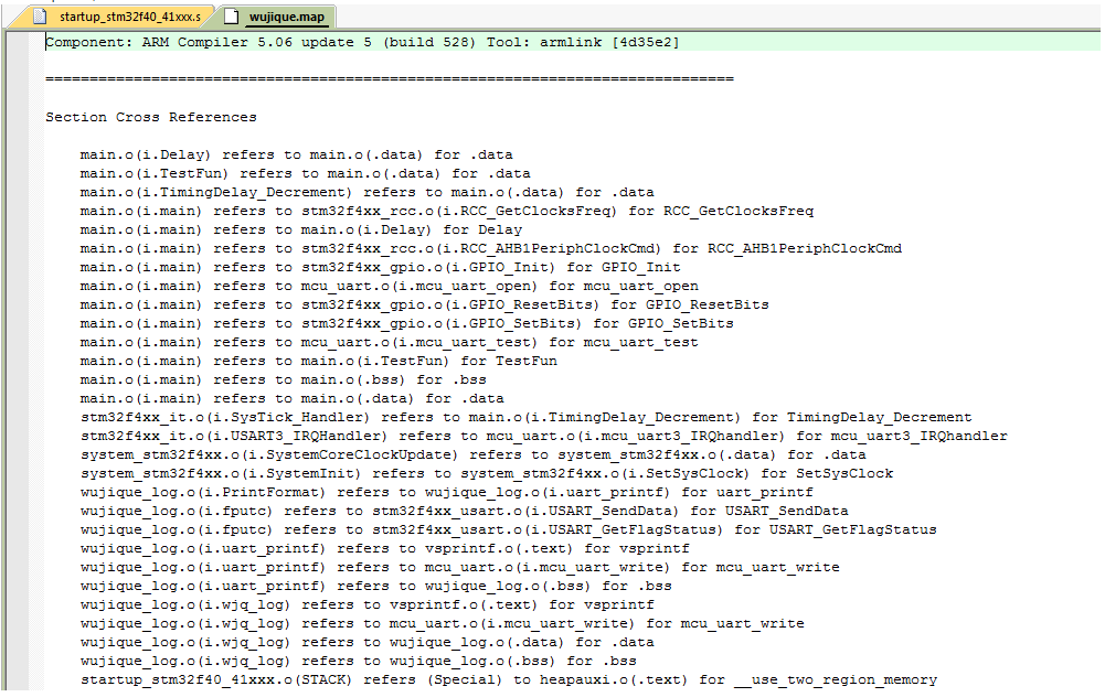
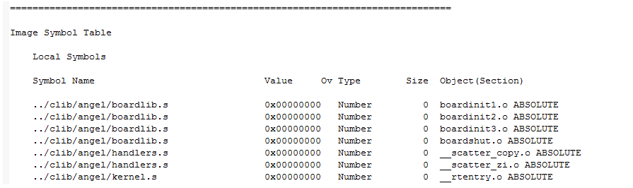
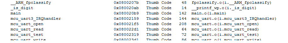
Image Symbol Table
The const modifier has multiple uses; it can modify variables as well as functions. More usage can be learned independently.

u8 TestFun(u32 x) // Function with one parameter, returning a u8 value { u8 test_tmp1 = 4; // Local variable, initialized u8 test_tmp2; // Local variable, uninitialized static u8 test_tmp3 = 0; // Static local variable}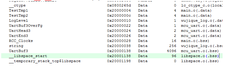
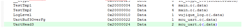
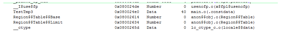
Code refers to code and functions. RO Data refers to read-only variables, such as arrays modified with const. RW Data refers to read-write variables, such as global variables and static modified local variables. ZI Data refers to read-write variables that are automatically initialized to 0 by the system, most of which are arrays and are placed in the bss segment. RO Size equals the sum of code and read-only variables. RW Size equals read-write variables (including those automatically initialized to 0); this is also the size of RAM. ROM Size refers to the size of the target file after compilation, which is also the size of FLASH. But why does it include RW Data? Because all global variables need an initialized value (even if not truly initialized, the system will allocate an initialization space). For example, if we define a variable u8 i = 8; this global variable, 8, needs to be stored in the FLASH area.

*(InRoot$$Sections)

Conclusion