By 2025, communication protocols such as I2C, SPI, and UART will remain a vital part of the tech world. These protocols facilitate communication between various electronic devices and serve as the invisible heart that keeps our interconnected embedded systems and peripherals running optimally.
In this article, we will dissect the functions, advantages, and limitations of these three protocols. We will first explore how each protocol operates, supplemented by explanatory GIFs for direct visualization. Next, we will compare I2C, SPI, and UART from different perspectives: speed, ease of use, and typical use cases.
1 I2C Protocol: Intuitive Communication
1.1 How I2C Works
I2C (Inter-Integrated Circuit) is a synchronous bidirectional serial communication protocol that operates in half-duplex mode, allowing multiple devices (masters or slaves) to be connected on the bus. Communication is always initiated by the master to one or more slaves, using two lines:
-
SDA (Serial Data Line) for data,
-
SCL (Serial Clock Line) for clock.
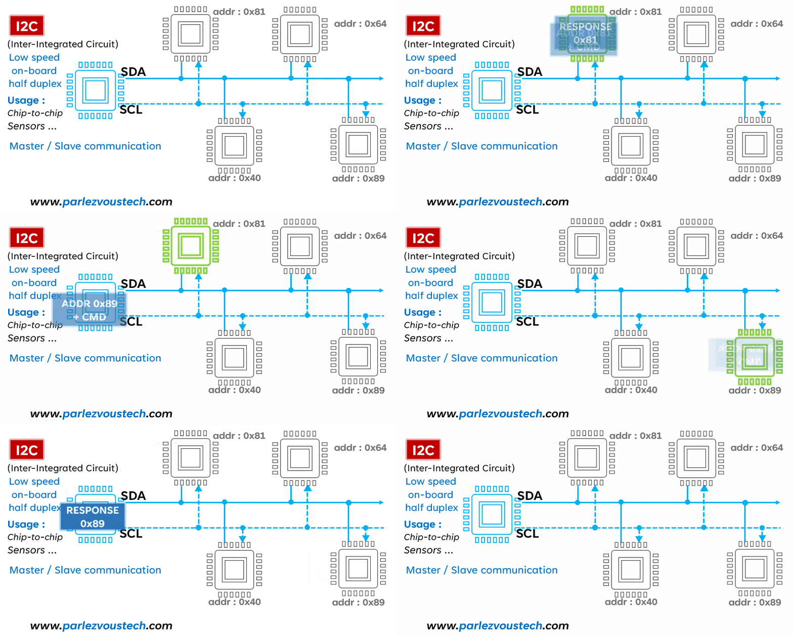
The above image demonstrates the basic I2C communication process, showing how the master initiates communication with the slave using its address, followed by commands. For better understanding, we have omitted some nuances, such as the acknowledgment after each data transfer.
1.2 I2C Operation: Read and Write
The I2C protocol is a bidirectional communication system divided into two main operations: reading (from master to slave) and writing (from slave to master), each following different key steps to ensure smooth and accurate data transmission.
1) Reading (Master to Slave):
-
1.START Condition: The reading starts with a START condition initiated by the master. This is achieved by pulling the data line (SDA) low while keeping the clock line (SCL) high. This distinct signal informs all devices on the bus that the master is about to start a new transmission.
-
2.Slave Address and Read Bit: The master then sends the address of the target slave on the bus, followed by a control bit set to 1 to indicate a read operation. Each bit is transmitted in sequence, changing on the rising edge of each clock pulse.
-
3.Acknowledgment (ACK/NACK): Upon receiving its address, the slave responds with an acknowledgment (ACK) bit by pulling the SDA line low for one clock cycle. A negative acknowledgment (NACK) is signaled by keeping the SDA line high.
-
4.Receiving Data: The slave then begins sending data to the master byte by byte.
-
5.Master Release: After receiving each byte, the master sends an acknowledgment (ACK) bit by pulling the SDA line low, signaling the slave to continue sending data. If the master does not wish to receive more data, it sends a NACK after the last byte received.
-
6.STOP Condition: Communication ends with a STOP condition. The master generates this signal by switching the SDA line from low to high while the SCL line is high. This change indicates the end of the read session and releases the bus for other communications.
2) Writing (Slave to Master):
-
1.START Condition: Similar to the reading process, writing starts with a START condition initiated by the master. This signal is generated by pulling the data line (SDA) low while keeping the clock line (SCL) high, indicating the start of the transmission.
-
2.Slave Address and Write Bit: The master then transmits the address of the slave to be written to, followed by a control bit set to 0 to indicate a write operation.
-
3.Acknowledgment (ACK/NACK): After receiving and recognizing its address, the slave sends an acknowledgment bit (ACK) by pulling the SDA line low for one clock cycle. A NACK is indicated by keeping the SDA line high.
-
4.Data Sent by Master: After receiving the ACK, the master begins sending data byte by byte.
-
5.Slave Acknowledgment: At the end of each byte sent, the slave confirms receipt by sending an acknowledgment bit (ACK), indicating successful reception of the byte. If there is an issue, it can send a NACK.
-
6.STOP/RESTART Condition: The operation ends with a STOP condition, generated by the master switching the SDA line from low to high while SCL is high, indicating the end of the bus transmission and release. If the master wishes to continue with another write or read operation, it can generate a RESTART condition.
Thus, this distinction between read and write modes in I2C allows for efficient bidirectional communication between devices connected to the bus.
1.3 Advantages, Disadvantages, and Use Cases
Advantages: Low pin consumption, using only two wires; allows communication with multiple slaves; relatively simple to set up and use.
Disadvantages: Limited speed compared to other protocols like SPI; sensitivity to interference over long distances; complexity increases with the number of slaves.
Applications: I2C shines in communication environments that require simplicity and cost-effectiveness, particularly excelling in integration with small sensors, LCD screens, and RTC (real-time clock) modules. Additionally, I2C is used in temperature control devices, battery management systems, and LED controllers due to its efficiency in compact circuits. However, for projects requiring fast or long-distance data transmission, other protocols are preferable.
2 SPI: High-Speed and Efficient
2.1 How SPI Works
SPI (Serial Peripheral Interface) is renowned for its high speed, making it the preferred choice for fast communication. Unlike I2C, SPI uses four lines: MISO (Master In Slave Out), MOSI (Master Out Slave In), SCK (Serial Clock), and SS (Slave Select), allowing for full-duplex communication (sending and receiving simultaneously). Although SPI is simple and fast, it requires more pins than I2C, which can be a consideration in circuit design.
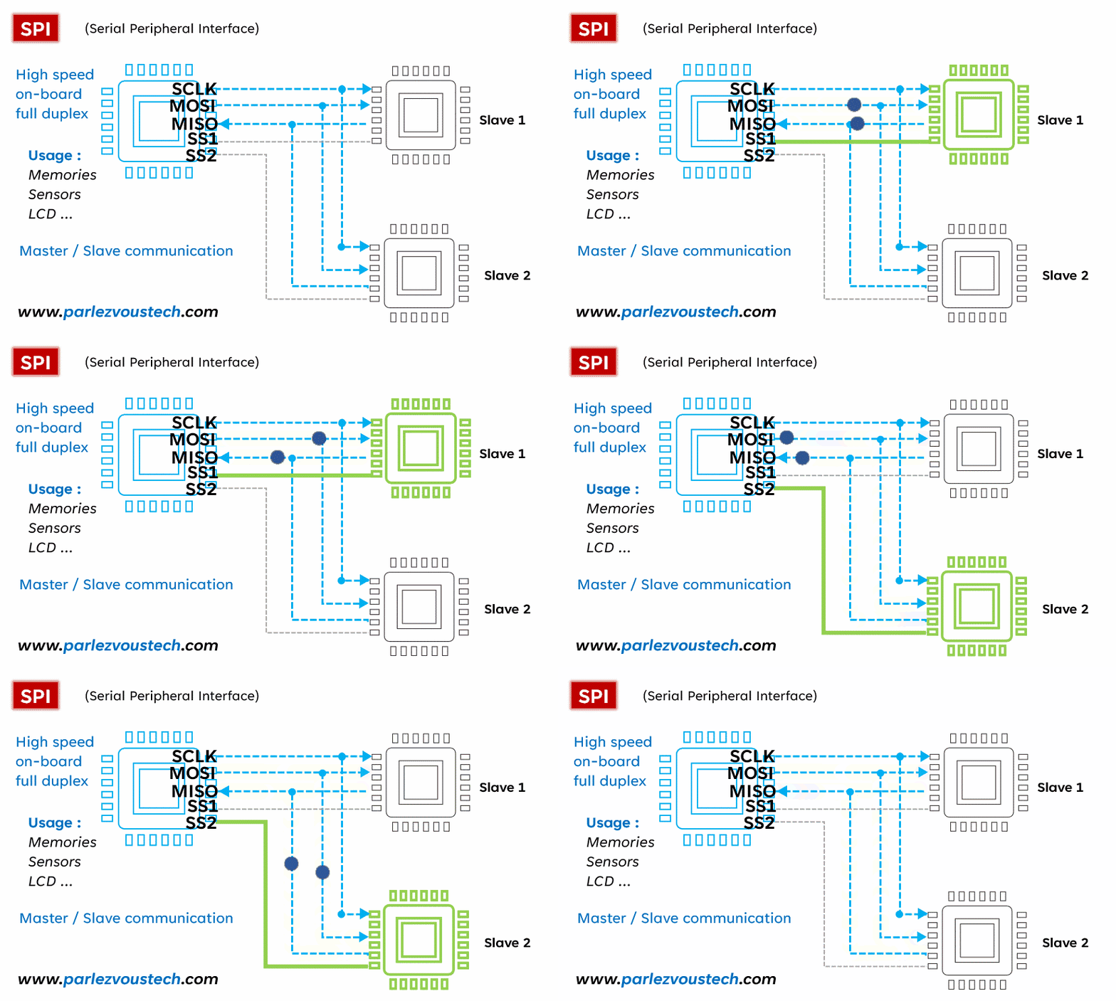
The above image illustrates a typical SPI communication process, showing how the master controls communication and data exchange with the selected slave. SPI transmission can be divided into the following stages:
-
1.Clock Signal Generation: The master initiates communication by generating a clock signal for synchronous data exchange.
-
2.Slave Selection: The master activates the desired slave by pulling the SS line low.
-
3.Data Exchange: The master first sends data to the slave via the MOSI line, bit by bit, usually starting from the most significant bit. Simultaneously, the slave can also send data to the master via the MISO line, typically starting from the least significant bit.
-
4.Simultaneous Communication: Unlike a simple command-response model, SPI allows for simultaneous bidirectional communication. As long as the SS line remains enabled, the master and slave can continue to exchange data simultaneously, achieving efficient and fast bidirectional data transmission.
2.2 Advantages, Disadvantages, and Applications
Advantages: Fast and efficient data transmission; full-duplex communication, allowing simultaneous sending and receiving; simple design and implementation.
Disadvantages: Uses multiple pins, which can be an issue in space-constrained designs; less efficient in managing multiple slaves compared to I2C; susceptible to interference at high speeds or over long distances.
Applications: SPI is well-suited for situations requiring fast and reliable data transmission, such as TFT displays, SD storage cards, and wireless communication modules. However, its effectiveness diminishes in complex systems with many slaves.
3 UART: A Universal Solution
3.1 How UART Works
UART (Universal Asynchronous Receiver/Transmitter) is a serial communication protocol widely used for its versatility and simplicity. Unlike I2C and SPI, UART operates with only two lines: TX (Transmit) and RX (Receive). This protocol allows for asynchronous communication, meaning there is no shared clock between the transmitter and receiver. Data is organized into packets, each containing a start bit, 5 to 9 data bits, an optional parity bit, and one or two stop bits.
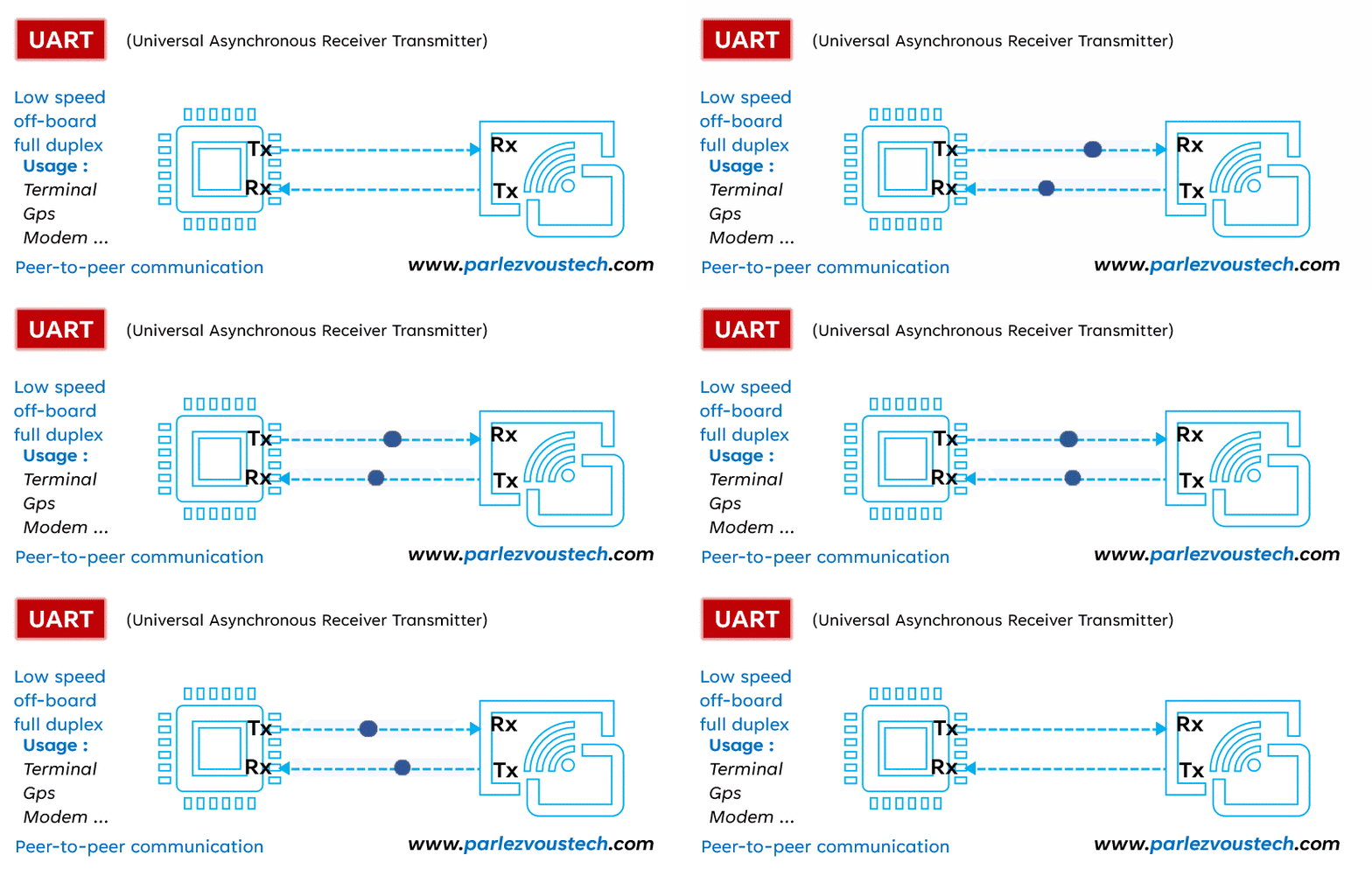
The detailed operation of UART is as follows:
-
1.High State Transmission Line: Typically, the transmission line remains at a high voltage level when no data is being transmitted.
-
2.Start Transmission: To begin transmission, the transmitter toggles the transmission line for one clock cycle. The UART receiver detects this voltage change and starts reading bits at the baud rate frequency.
-
3.Baud Rate: The baud rate, which measures data transmission speed, should be approximately the same for both UARTs. Common baud rates include 9600, 19200, 38400, 57600, and 115200 bits per second. The baud rate difference between two UARTs should not exceed 10%.
-
4.Data Frame: The frame contains the actual data being transmitted, usually starting with the least significant bit.
-
5.Parity Bit: The parity bit is used for error detection, allowing the receiving UART to determine if any changes occurred during transmission.
-
6.Stop Bit: To signal the end of a data packet, the transmitting UART raises the transmission line to a high level for at least two bit durations.
3.2 Advantages, Disadvantages, and Applications
Advantages: Simple, requiring only two wires; flexible due to the lack of a clock signal; uses parity bits for error detection.
Disadvantages: Limits data frame size to a maximum of 9 bits; not suitable for systems with multiple slaves or masters; reliable communication requires similar baud rates.
Applications: UART is widely used for point-to-point communication in various fields, such as connections between microcontrollers and peripherals for simple and direct data exchange; GPS modules and serial interfaces with computers for reliable, low-complexity communication, etc.
4 Comparative Analysis: I2C, SPI, and UART
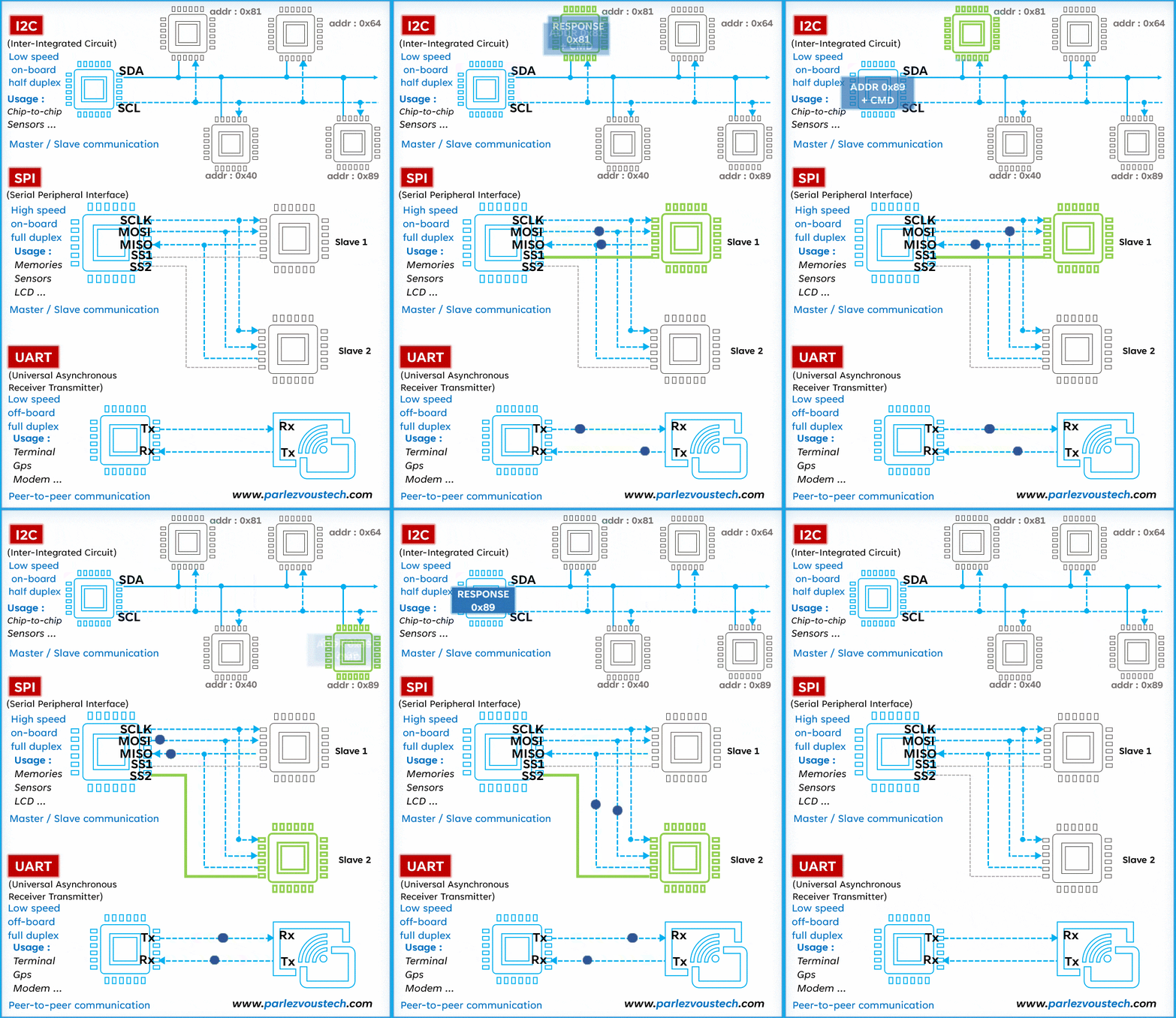
The comparative summary of these three protocols is as follows:
|
Feature |
I2C |
SPI |
UART |
|
Speed |
Average (up to a few Mbit/s) |
High (from a few Mbit/s to tens of Mbit/s) |
Medium (lower than SPI) |
|
Complexity |
Medium (2 wires, managing multiple slaves) |
Medium-High (4 wires, full-duplex) |
Medium (2 wires, full-duplex) |
|
Use |
Very suitable for short-distance communication with multiple devices |
Very suitable for fast data transmission |
Suitable for simple and long-distance serial communication |
|
Duplex |
Half-duplex (bidirectional communication, but not simultaneous) |
Full-duplex (synchronous bidirectional communication) |
Full-duplex (synchronous bidirectional communication) |
When considering how to choose the right protocol, the following points should be noted:
-
1.
Communication Speed: SPI for speed, UART for flexibility, I2C for configurations with lower speed requirements.
-
2.Circuit Design: I2C for efficient space management with multiple devices, SPI for performance in large designs, UART for simplicity and versatility.
-
3.Distance and Communication Environment: UART is robust over long distances, while I2C is better suited for short distances.
-
4.Duplex Requirements: SPI and UART provide full-duplex capabilities, while I2C is limited to half-duplex.
By considering these factors, one can better choose the protocol that best meets the project requirements.
5 Conclusion
Through this article, we explored the nuances and peculiarities of three major communication protocols: I2C, SPI, and UART. Each of them offers a unique balance between speed, complexity, availability, and duplex capabilities, providing different solutions to communication challenges in electronic projects.
-
I2C stands out for its simplicity and ability to manage multiple slaves with minimal pins, making it an ideal choice for short-distance configurations.
-
SPI, with its high speed and full-duplex mode, is excellent for fast and efficient data transmission in systems where space is not a major concern.
-
UART is versatile and robust, excelling in long-distance communication and configurations with lower speed requirements.