Source: https://blog.csdn.net/weixin_48426161
1. Add Header Files
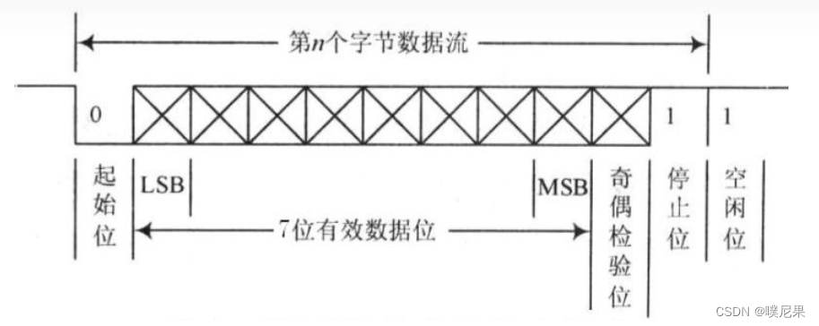
First, we need to add the corresponding header files. Since we are going to simulate the serial port, we need to understand the UART communication protocol. The UART communication method consists of 1 start bit, 8 data bits, an optional parity bit, and a stop bit. Therefore, we will use two ordinary I/O pins in the microcontroller to simulate the corresponding timing.
#include "stm32f10x.h"
#include "vuart2.h"
2. Macro Definitions
The I/O ports used are
#define OI2_TXD PDout(6)
#define OI2_RXD PDin(7)

#define BuadRate2_9600 104
#define Recive2_Byte 19 // Number of items in the receive buffer
u8 len2 = 0; // Receive count
u8 USART2_buf[Recive2_Byte];  // Receive buffer
We define macros for the I/O port bit operations to make it easier to convert different levels and reduce the time consumed by calling other functions, thus improving program execution efficiency.
In this transmission process, I chose to use a baud rate of 9600, which means sending 9600 bytes in 1 second. Therefore, calculating 1000000us/9600 gives approximately 104.16us needed to send one byte of data. The duration error for the corresponding levels cannot exceed ±5%, so controlling the timing is quite important.
3. Enumerate Each Bit
enum{
    COM_START_BIT,
    COM_D0_BIT,
    COM_D1_BIT,
    COM_D2_BIT,
    COM_D3_BIT,
    COM_D4_BIT,
    COM_D5_BIT,
    COM_D6_BIT,
    COM_D7_BIT,
    COM_STOP_BIT,
};

u8 recvStat2 = COM_STOP_BIT;
u8 recvData2 = 0;
4. Simulate IO—TXD
void IO2_TXD(u8 Data)
{
    u8 i = 0;
    OI2_TXD = 0;
    delay_us(BuadRate2_9600);
    for(i = 0; i < 8; i++)
    {
        if(Data & 0x01)
            OI2_TXD = 1;
        else
            OI2_TXD = 0;

        delay_us(BuadRate2_9600);
        Data = Data >> 1;
    }
    OI2_TXD = 1;
    delay_us(BuadRate2_9600);
}
Since the sent signal pulls down the TXD signal, after pulling down the corresponding I/O port, a delay is processed, then the loop continues to send the data of each bit. After sending is completed, the level is pulled high to represent the stop bit.
5. Build Send Function
void USART2_Send(u8 *buf, u8 len2)
{
    u8 t;
    for(t = 0; t < len2; t++)
    {
        IO2_TXD(buf[t]);
    }
}
The *buf is the data to be sent, and len2 is the data length, which calls IO_TXD in a loop to send data byte by byte.
6. IO Port Initialization
void IO2Config(void)
 {
    GPIO_InitTypeDef  GPIO_InitStructure; // Initialize GPIO
    NVIC_InitTypeDef NVIC_InitStructure; // Interrupt initialization function
     EXTI_InitTypeDef EXTI_InitStruct;
    RCC_APB2PeriphClockCmd(RCC_APB2Periph_AFIO|RCC_APB2Periph_GPIOD|RCC_APB2Periph_GPIOC, ENABLE);  // Enable PD, PC port clock

     // Software Serial TXD
    GPIO_InitStructure.GPIO_Pin = GPIO_Pin_6;       // Select I/O port 6
    GPIO_InitStructure.GPIO_Mode = GPIO_Mode_Out_PP;    // Push-pull output
    GPIO_InitStructure.GPIO_Speed = GPIO_Speed_50MHz;   // I/O port speed is 50MHz
    GPIO_Init(GPIOD, &GPIO_InitStructure);
    GPIO_SetBits(GPIOD, GPIO_Pin_6);       // TXD default level high

    // Software Serial RXD
    GPIO_InitStructure.GPIO_Pin = GPIO_Pin_7;
    GPIO_InitStructure.GPIO_Mode = GPIO_Mode_IPU;
    GPIO_InitStructure.GPIO_Speed = GPIO_Speed_50MHz;
    GPIO_Init(GPIOD, &GPIO_InitStructure);

    GPIO_EXTILineConfig(GPIO_PortSourceGPIOD, GPIO_PinSource7);  // Trigger interrupt sampling on the falling edge of D7, indicating data reception
    EXTI_InitStruct.EXTI_Line = EXTI_Line7; // Using interrupt 7
    EXTI_InitStruct.EXTI_Mode=EXTI_Mode_Interrupt;
    EXTI_InitStruct.EXTI_Trigger=EXTI_Trigger_Falling; // Falling edge trigger interrupt
    EXTI_InitStruct.EXTI_LineCmd=ENABLE;
    EXTI_Init(&EXTI_InitStruct); // Initialize interrupt

    NVIC_InitStructure.NVIC_IRQChannel= EXTI9_5_IRQn ; // Interrupt occurs in 9-5
    NVIC_InitStructure.NVIC_IRQChannelPreemptionPriority=2;
    NVIC_InitStructure.NVIC_IRQChannelSubPriority =2;
    NVIC_InitStructure.NVIC_IRQChannelCmd=ENABLE;
    NVIC_Init(&NVIC_InitStructure);
}
7. Timer Initialization
void TIM5_Int_Init(u16 arr,u16 psc)
{
    TIM_TimeBaseInitTypeDef  TIM_TimeBaseStructure;
    NVIC_InitTypeDef NVIC_InitStructure;
    RCC_APB1PeriphClockCmd(RCC_APB1Periph_TIM5, ENABLE); // Enable clock

    // Timer TIM5 initialization
    TIM_TimeBaseStructure.TIM_Period = arr; // Set the value loaded into the active auto-reload register for the next update event
    TIM_TimeBaseStructure.TIM_Prescaler = psc; // Set the prescaler value to divide the TIMx clock frequency
    TIM_TimeBaseStructure.TIM_ClockDivision = TIM_CKD_DIV1; // Set clock division: TDTS = Tck_tim
    TIM_TimeBaseStructure.TIM_CounterMode = TIM_CounterMode_Up;  // TIM counting up mode
    TIM_TimeBaseInit(TIM5, &TIM_TimeBaseStructure); // Initialize TIMx time base unit according to specified parameters
    TIM_ClearITPendingBit(TIM5, TIM_FLAG_Update);
    TIM_ITConfig(TIM5,TIM_IT_Update, ENABLE); // Enable specified TIM5 interrupt, allow update interrupt

    // Interrupt priority NVIC settings
    NVIC_InitStructure.NVIC_IRQChannel = TIM5_IRQn;  // TIM5 interrupt
    NVIC_InitStructure.NVIC_IRQChannelPreemptionPriority = 1;  // Preemption priority level 1
    NVIC_InitStructure.NVIC_IRQChannelSubPriority = 1;  // Sub-priority level 1
    NVIC_InitStructure.NVIC_IRQChannelCmd = ENABLE; // IRQ channel enabled
    NVIC_Init(&NVIC_InitStructure);  // Initialize NVIC register
}
Initializing TIM5 allows the timer to detect the duration of each bit’s level, thus analyzing the received data. After the timing ends, it enters the TIM5 interrupt handling.
8. External Interrupt Handler
void EXTI9_5_IRQHandler(void)
{
    if(EXTI_GetFlagStatus(EXTI_Line7) != RESET) // Collect interrupt flag
    {
        if(OI2_RXD == 0)
        {
            if(recvStat2 == COM_STOP_BIT)
            {
                recvStat2 = COM_START_BIT; // Set current status to start bit
                TIM_Cmd(TIM5, ENABLE); // Start timer counting
            }
        }
        EXTI_ClearITPendingBit(EXTI_Line7); // Clear interrupt flag
    }
}
9. Timer Interrupt Handler
void TIM5_IRQHandler(void)
{
    if(TIM_GetFlagStatus(TIM5, TIM_FLAG_Update) != RESET)
    {
        TIM_ClearITPendingBit(TIM5, TIM_FLAG_Update); // Clear interrupt flag
        recvStat2++; // Move position to first bit of data
        if(recvStat2 == COM_STOP_BIT) // When reaching the stop bit, enter
        {
            TIM_Cmd(TIM5, DISABLE); // Stop TIM5
            USART2_buf[len2++] = recvData2; // Pass collected data to USART2_buf
            if(len2 > Recive2_Byte-1) // Echo data to serial port debugging assistant
            {
                len2 = 0;
                USART2_Send(USART2_buf, Recive2_Byte);
            }
            return;
        }
        if(OI2_RXD) // Collect RXD levels
        {
            recvData2 |= (1 << (recvStat2 - 1));
        }else{
            recvData2 &= ~(1 << (recvStat2 - 1));
        }
  }
}
Complete Code
vuart2.c
#include "stm32f10x.h"
#include "vuart2.h"
/**
* Implementation of software serial port (IO simulated serial port)
* Baud rate: 9600    1-8-N
* TXD : PD6
* RXD : PD7
* Use external interrupt to trigger on the falling edge of RXD, use Timer 5 to time data reception at 9600 baud rate.
* Demo function: Receive 11 data, then send the received data out
*/

#define OI2_TXD PDout(6)
#define OI2_RXD PDin(7)

#define BuadRate2_9600 104
#define Recive2_Byte 19 // Number of items in the receive buffer
u8 len2 = 0; // Receive count
u8 USART2_buf[Recive2_Byte];  // Receive buffer

enum{
    COM_START_BIT,
    COM_D0_BIT,
    COM_D1_BIT,
    COM_D2_BIT,
    COM_D3_BIT,
    COM_D4_BIT,
    COM_D5_BIT,
    COM_D6_BIT,
    COM_D7_BIT,
    COM_STOP_BIT,
};

u8 recvStat2 = COM_STOP_BIT;
u8 recvData2 = 0;

void IO2_TXD(u8 Data)
{
    u8 i = 0;
    OI2_TXD = 0;
    delay_us(BuadRate2_9600);
    for(i = 0; i < 8; i++)
    {
        if(Data & 0x01)
            OI2_TXD = 1;
        else
            OI2_TXD = 0;

        delay_us(BuadRate2_9600);
        Data = Data >> 1;
    }
    OI2_TXD = 1;
    delay_us(BuadRate2_9600);
}

void USART2_Send(u8 *buf, u8 len2)
{
    u8 t;
    for(t = 0; t < len2; t++)
    {
        IO2_TXD(buf[t]);
    }
}

 void IO2Config(void)
 {
    GPIO_InitTypeDef  GPIO_InitStructure;
    NVIC_InitTypeDef NVIC_InitStructure;
     EXTI_InitTypeDef EXTI_InitStruct;
    RCC_APB2PeriphClockCmd(RCC_APB2Periph_AFIO|RCC_APB2Periph_GPIOD|RCC_APB2Periph_GPIOC, ENABLE);  // Enable PB, PC port clock

     // Software Serial TXD
    GPIO_InitStructure.GPIO_Pin = GPIO_Pin_6;
    GPIO_InitStructure.GPIO_Mode = GPIO_Mode_Out_PP;    // Push-pull output
    GPIO_InitStructure.GPIO_Speed = GPIO_Speed_50MHz;   // I/O port speed is 50MHz
    GPIO_Init(GPIOD, &GPIO_InitStructure);
    GPIO_SetBits(GPIOD, GPIO_Pin_6);       // TXD default level high

    // Software Serial RXD
    GPIO_InitStructure.GPIO_Pin = GPIO_Pin_7;
    GPIO_InitStructure.GPIO_Mode = GPIO_Mode_IPU;
    GPIO_InitStructure.GPIO_Speed = GPIO_Speed_50MHz;
    GPIO_Init(GPIOD, &GPIO_InitStructure);

    GPIO_EXTILineConfig(GPIO_PortSourceGPIOD, GPIO_PinSource7);
    EXTI_InitStruct.EXTI_Line = EXTI_Line7;
    EXTI_InitStruct.EXTI_Mode=EXTI_Mode_Interrupt;
    EXTI_InitStruct.EXTI_Trigger=EXTI_Trigger_Falling; // Falling edge trigger interrupt
    EXTI_InitStruct.EXTI_LineCmd=ENABLE;
    EXTI_Init(&EXTI_InitStruct);


    NVIC_InitStructure.NVIC_IRQChannel= EXTI9_5_IRQn ;
    NVIC_InitStructure.NVIC_IRQChannelPreemptionPriority=2;
    NVIC_InitStructure.NVIC_IRQChannelSubPriority =2;
    NVIC_InitStructure.NVIC_IRQChannelCmd=ENABLE;
    NVIC_Init(&NVIC_InitStructure);
}

void TIM5_Int_Init(u16 arr,u16 psc)
{
    TIM_TimeBaseInitTypeDef  TIM_TimeBaseStructure;
    NVIC_InitTypeDef NVIC_InitStructure;
    RCC_APB1PeriphClockCmd(RCC_APB1Periph_TIM5, ENABLE); // Enable clock

    // Timer TIM5 initialization
    TIM_TimeBaseStructure.TIM_Period = arr; // Set the value loaded into the active auto-reload register for the next update event
    TIM_TimeBaseStructure.TIM_Prescaler = psc; // Set the prescaler value to divide the TIMx clock frequency
    TIM_TimeBaseStructure.TIM_ClockDivision = TIM_CKD_DIV1; // Set clock division: TDTS = Tck_tim
    TIM_TimeBaseStructure.TIM_CounterMode = TIM_CounterMode_Up;  // TIM counting up mode
    TIM_TimeBaseInit(TIM5, &TIM_TimeBaseStructure); // Initialize TIMx time base unit according to specified parameters
    TIM_ClearITPendingBit(TIM5, TIM_FLAG_Update);
    TIM_ITConfig(TIM5,TIM_IT_Update,ENABLE ); // Enable specified TIM5 interrupt, allow update interrupt

    // Interrupt priority NVIC settings
    NVIC_InitStructure.NVIC_IRQChannel = TIM5_IRQn;  // TIM4 interrupt
    NVIC_InitStructure.NVIC_IRQChannelPreemptionPriority = 1;  // Preemption priority level 1
    NVIC_InitStructure.NVIC_IRQChannelSubPriority = 1;  // Sub-priority level 1
    NVIC_InitStructure.NVIC_IRQChannelCmd = ENABLE; // IRQ channel enabled
    NVIC_Init(&NVIC_InitStructure);  // Initialize NVIC register
}
void EXTI9_5_IRQHandler(void)
{
    if(EXTI_GetFlagStatus(EXTI_Line7) != RESET)
    {
        if(OI2_RXD == 0)
        {
            if(recvStat2 == COM_STOP_BIT)
            {
                recvStat2 = COM_START_BIT;
                TIM_Cmd(TIM5, ENABLE);
            }
        }
        EXTI_ClearITPendingBit(EXTI_Line7);
    }
}

void TIM5_IRQHandler(void)
{
    if(TIM_GetFlagStatus(TIM5, TIM_FLAG_Update) != RESET)
    {
        TIM_ClearITPendingBit(TIM5, TIM_FLAG_Update);
        recvStat2++;
        if(recvStat2 == COM_STOP_BIT)
        {
            TIM_Cmd(TIM5, DISABLE);
            USART2_buf[len2++] = recvData2;
        if(len2 > Recive2_Byte-1)
        {
            len2 = 0;
            USART2_Send(USART2_buf, Recive2_Byte);
        }
            return;
        }
        if(OI2_RXD)
        {
            recvData2 |= (1 << (recvStat2 - 1));
        }else{
            recvData2 &= ~(1 << (recvStat2 - 1));
        }
  }
}
vuart2.h
#ifndef __VUART2__H
#define __VUART2__H
#include "stm32f10x.h"

void IO2_TXD(u8 Data);
void USART2_Send(u8 *buf, u8 len);
void IO2Config(void);
void TIM5_Int_Init(u16 arr,u16 psc);
#endif
This article is sourced from the internet, freely conveying knowledge, copyright belongs to the original author. If there are copyright issues, please contact me for deletion.
Note
Due to recent changes in WeChat official account push rules, to prevent being unable to find it, you can star it for top placement, so that the articles pushed each time will appear in your subscription list.
You may also like:
Share an embedded software tool list!
Easy to understand | A step-by-step guide to writing your first upper computer
Practical | Teach you to build an embedded web server in 10 minutes
Embedded common communication protocols animated, collect!
Universal library for differential upgrades suitable for embedded systems!
Share a highly flexible protocol format (with code examples)
Share several practical code snippets (second edition)
Reply 1024 in the public account chat interface to get embedded resources; reply m to view article summary