This is an SPI Flash chip: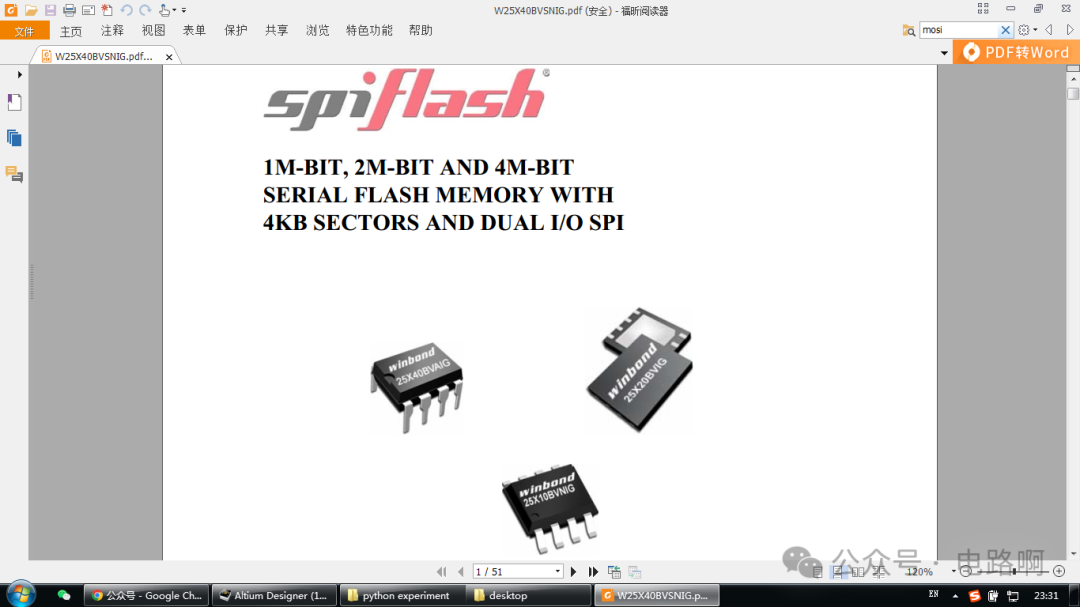
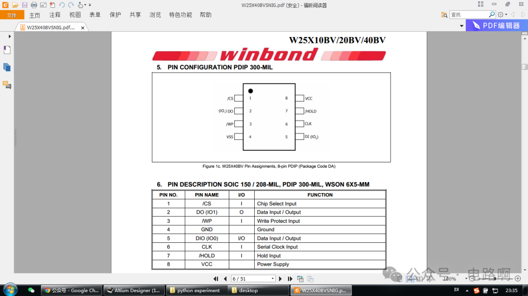
The pin definitions in its datasheet are as follows:
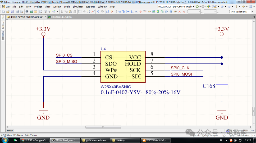
The circuit schematic of this SPI Flash chip:
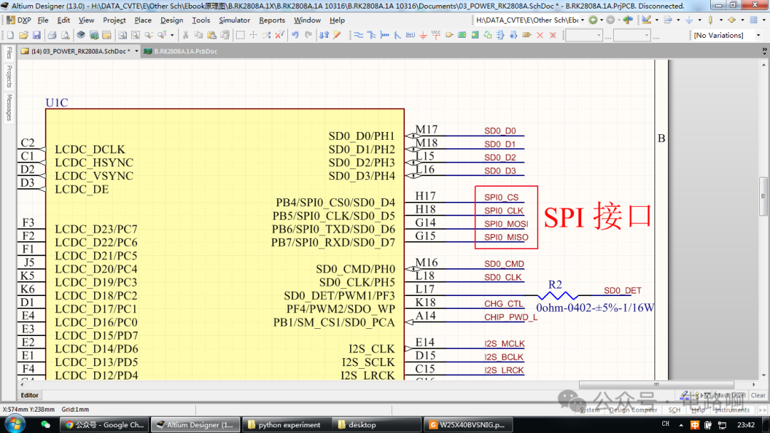
It connects to the SPI interface on the main control chip:
The SPI interface is very common, and below I will try to explain what the SPI interface is in simple terms.
The SPI (Serial Peripheral Interface) is a commonly used high-speed, full-duplex, synchronous communication bus. For analogy, you can think of the SPI interface as a “highway” used to transmit information within electronic devices, where the “cars” are data.
1. Composition of the SPI Interface
The SPI interface generally has 4 lines: 1. Clock line (SCK): Like a conductor, it controls the rhythm of data transmission, telling the devices when to send data and when to receive data. 2. Master Out Slave In (MOSI): If your device is the “leader” (master device), it sends data to other devices (slave devices) through this line. 3. Master In Slave Out (MISO): Conversely, when the slave device wants to send feedback data to the master device, it does so through this line. 4. Slave Select line (SS or CS): The master device uses this line to select which slave device to communicate with, like calling a roll; only the selected slave device starts working.
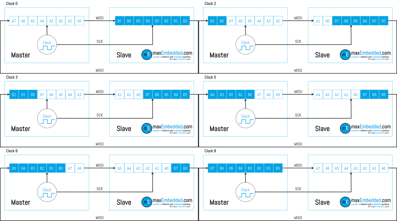
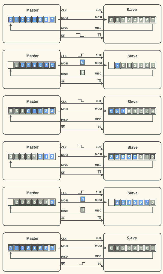
2. SPI Interface ProtocolThe SPI protocol is a communication protocol based on a master-slave architecture. In an SPI system, there must be one master device and multiple slave devices can be connected. 1. Data Transmission Mode: SPI supports full-duplex data transmission, meaning the master device can send data to the slave device while the slave device can also send data back to the master device at the same time. This efficient transmission method greatly increases the speed of data exchange. 2. Clock Polarity (CPOL) and Clock Phase (CPHA): Clock polarity (CPOL) determines whether the clock signal is high or low when idle. When CPOL = 0, the clock signal is low when idle; when CPOL = 1, the clock signal is high when idle. Clock phase (CPHA) determines whether data is sampled on the first or second edge of the clock. When CPHA = 0, data is sampled on the first edge of the clock; when CPHA = 1, data is sampled on the second edge of the clock. Through different combinations of CPOL and CPHA, the SPI protocol defines 4 different working modes to accommodate the needs of different devices. 3. Data Transmission Format: In the SPI protocol, data is transmitted byte by byte. The master device and the slave device must agree on the number of bits (usually 8 bits) and the order of transmission (whether high bits first or low bits first) before data transmission occurs. Under the drive of the clock signal, data is transmitted bit by bit over the MOSI and MISO lines.
3. Signal Timing
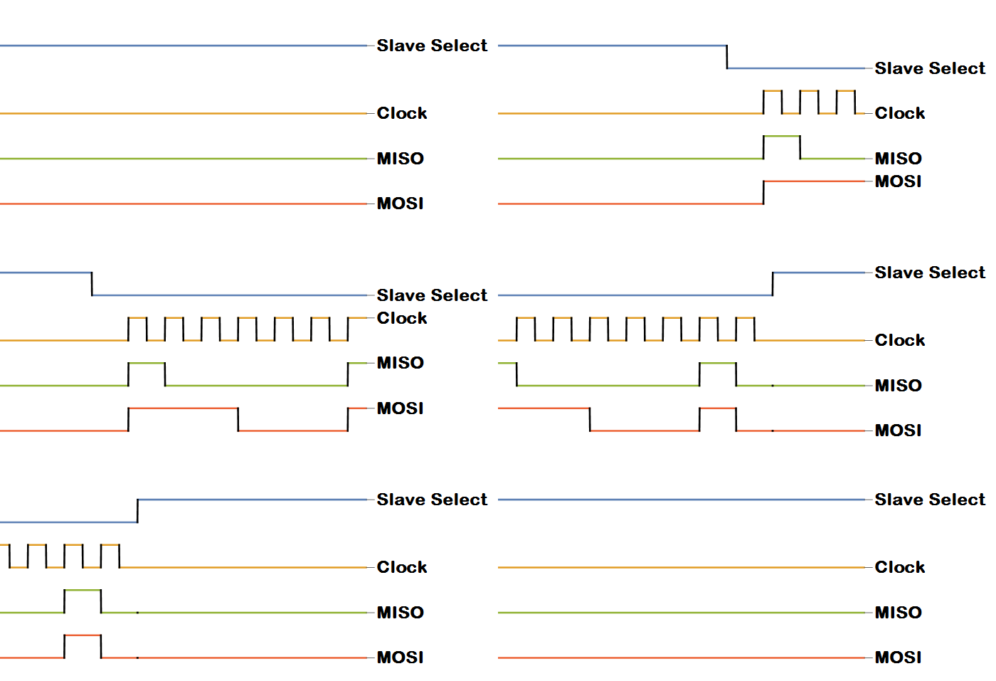
1. When the master device wants to communicate with a particular slave device, it first pulls the corresponding slave select line (SS or CS) low to select that slave device. 2. Then the master device starts sending clock pulse signals on the clock line (SCK). Data transmission occurs alongside the clock pulses; at each rising or falling edge of the clock pulse (depending on the configured mode), the master device sends one bit of data through the MOSI line, while the slave device prepares to receive data at that moment; similarly, the slave device sends one bit of data to the master device through the MISO line, which the master device receives at the corresponding moment. 3. This continues, transmitting one bit at a time until all the data to be transmitted is sent. After transmission, the master device pulls the slave select line (SS or CS) high to indicate that the communication is over, and the slave device returns to a waiting state for “roll call”.
4. Applications of SPI InterfaceThe SPI interface has a wide range of applications in electronic devices.
For example, in the sensor field, many sensors such as accelerometers and gyroscopes use the SPI interface to communicate with microcontrollers, allowing the collected data to be transmitted quickly and accurately to the microcontroller for processing.
In terms of memory, some flash memory chips also use the SPI interface for data exchange with the master device, facilitating data storage and retrieval operations. The beginning of this article is derived from the flash memory chip to explain what the SPI interface is. I hope this article on the SPI interface and its protocol provides a clearer understanding of it.
If you find the article good, please like and share, thank you all!