Click the above “Embedded and Linux Matters”, select “Pin/Star Public Account”
Welfare and dry goods delivered first-hand
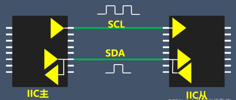
Generally speaking, there are usually no problems with soldering i2c devices. If you follow the device manual step by step, it should work smoothly. However, if such a simple thing sometimes does not yield the desired results, and after repeatedly checking for issues, consulting solutions, verifying the data manual, and understanding the meaning of every command and data sent and received, the problem still cannot be resolved, what should you do?
This article mainly focuses on i2c devices, explaining how to solve the problem of normal data interaction between the i2c master and slave. The emphasis is on issues caused by unreasonable hardware design or non-standard i2c device design leading to bus faults, and proposing solutions through phenomenon analysis.
For cases where the desired data cannot be obtained due to not setting the appropriate registers or sending commands during device initialization, no detailed introduction will be provided.
1. Basic Usage of I2C
The i2c bus is a simple, bidirectional two-wire synchronous serial bus. All masters generate their own clocks on the SCL line to transmit messages on the bus, and the SDA line transmits each byte, which must be 8 bits. The number of bytes that can be sent in each transmission is unlimited, but each byte must be followed by an acknowledgment bit. In idle state, both SCL and SDA are high.
Typically, some low-power i2c devices can use pull-up outputs on chip pins to facilitate normal data interaction. Other i2c devices may require an external pull-up resistor on the bus, at which point the corresponding I/O should be configured as open-drain output, with other configurations following the chip manual.
2. Summary of Hardware Issues
2.1 Unable to Pull High or Low Pins Normally
First, confirm that the SDA and SCL pins can be pulled high and low by directly controlling the I/O port output to low/high levels and measuring whether the pin voltage can correspond to the state output by the chip pin settings.
If it cannot be pulled low, check for cold solder joints, open pull-up resistors, whether the i2c device is functioning properly, or if the chip pins are damaged, ensuring they can be pulled high or low normally.
2.2 Electrical Characteristics Not Met
If data cannot be read normally despite being pulled high and low correctly, it is usually recommended to replace with a lower resistance based on the load current.
To understand the reasons in detail, refer to the electrical characteristics of the i2c device. Most i2c device electrical characteristics are roughly illustrated in the following figure:

This section primarily explains the longest and shortest time for levels to be pulled high or low, as well as the thresholds and durations for high and low levels.
In hardware design, to reduce the power consumption of the microcontroller and protect the chip pins, the resistance values are usually set quite high while meeting the related requirements for load current and capacitance. If multiple i2c devices are connected on the same bus, even with correct I/O configurations, it may lead to insufficient driving capability.
The phenomenon is insufficient pull-up voltage, with excessive time consumption during high and low transitions. These issues often also lead to data and clock lines: during pull-up, the high voltage duration is too short; during pull-down, the low voltage duration is too short.
Using an oscilloscope to capture the waveform, it shows spikes, sloped waves, noise, etc., which do not conform to the electrical characteristics of i2c devices; from the data perspective, the duration of high levels on the data line is too short, rise time is too long, fall time is too long, etc., all exceeding the effective values of the device’s electrical characteristics.
Typical noise graphs are shown below:
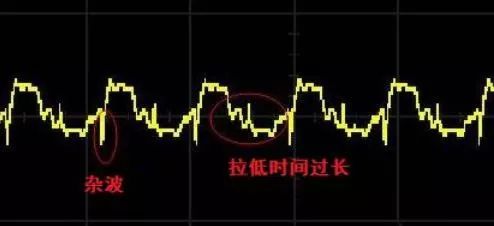
If such anomalies occur, it is recommended to replace with smaller resistors to enhance bus driving capability and improve level conversion speed. It should be noted that each MCU has different tolerable currents, and reducing resistance should avoid exceeding the maximum current that the corresponding pin can handle.
3. SDA Deadlock
If the i2c device occasionally retrieves data correctly but still encounters bus read/write errors when sending data or commands, it may be facing a deadlock issue, where the data line is pulled low, preventing the master from pulling it high.
Deadlocks generally occur on the slave side, specifically on the data line. Since the i2c bus is shared, to determine if it is a slave deadlock, you can refer to the two diagrams below and test with series resistors:
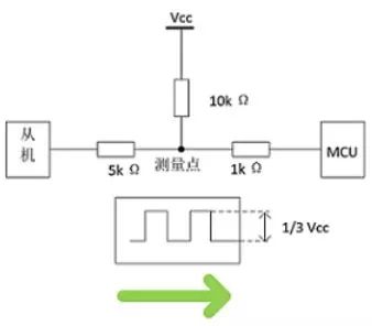
As shown in the figure above, if the slave is deadlocked, pulling the low level will result in a detected voltage of 1/3 Vcc.
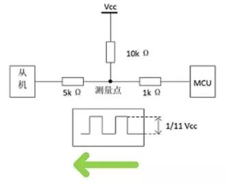
As shown in the figure above, if the master is deadlocked, pulling the low level will result in a detected voltage of 1/11 Vcc. Based on this principle, the specific location of the deadlock can be accurately determined, allowing multiple sensors to locate similarly.
3.1 Repeated Restarts Leading to Deadlock
3.1.1 Phenomenon
If the device requires repeated restarts, it is very likely that the SDA is locked when the slave device returns data. The specific reason is that when the slave device is returning data and has not yet completed sending, the master clock disappears, and the slave waits for the clock signal. If the MCU restarts without resetting the slave device’s power, the slave continues to wait for the MCU’s clock signal, causing the data to be trapped, and the bus cannot complete data interaction.
3.1.2 Solution
To resolve the deadlock caused by restarts, one method is similar to the RT-Thread driver’s solution, where nine clock signals are provided during system reset to unlock the deadlock; another method is to power cycle the slave device upon pressing the reset button, which requires pin control.
3.1.3 Nine Clock Signals
During the read/write operation of the i2c device, if the slave locks the bus while the MCU resets abnormally, it will lead to an SDA deadlock. The anomalies occur in two stages: the slave response stage and the slave data sending stage. Below, the clock signals will be explained for these two types of anomalies, along with a summary of other reasons to draw conclusions.
(a) Slave Response Stage
After the MCU sends the address following the start signal and receives a response from the slave device, preparing to return data, at this point, the slave pulls the SDA signal low. If the MCU resets abnormally, it will cause the SCL on the bus to stop sending clock signals. The slave waits for the MCU’s clock signal, resulting in the phenomenon of locking and pulling the SDA low. To unlock the SDA, the slave requires nine clock signals to complete the response and release the SDA.
(b) Slave Data Sending Stage
If the slave has completed the response and begins to return data to the MCU, this data consists of eight bits, and each bit can be low. If during the low data bit, the MCU resets abnormally and stops sending clock signals, the slave will wait for the MCU’s clock signal, leading to the phenomenon of locking and pulling the SDA low. To unlock the SDA, the slave requires 1-8 clock signals to complete the data response and release the SDA.
(c) Other Situations
After the slave completes sending an 8-bit data, it waits for the MCU’s response. Even if it belongs to the MCU, the slave no longer locks the SDA, and without a clock, data interaction stops.
During the master data sending stage, the bus is under the control of the master. If the master malfunctions, data interaction stops, and the bus is released. Therefore, in these situations, there is no SDA deadlock.
(d) Conclusion
In summary, to unlock the SDA, the slave requires up to nine clock signals, meaning that after an abnormal reset, the MCU must send at least nine clock signals to complete the unlocking of the i2c bus SDA. Therefore, to avoid such issues, RT_Thread checks the bus during i2c driver initialization to determine if unlocking is necessary. If so, it performs the unlocking to ensure that i2c devices do not fail data interaction due to this problem.
3.2 Multiple i2c Devices Leading to Deadlock
In addition to abnormal resets causing deadlocks, multiple i2c devices can also interfere with each other. Generally, the same type of slave address is not connected on the same bus, but beyond that, some i2c devices are not designed according to standard i2c bus protocols. Under the premise of sharing the i2c bus, some devices will respond as long as there is a slave address on the bus. Due to incorrect responses from the slaves, various i2c buses can malfunction or even lock the bus, leading to a deadlock state on the I2C bus.
Solution: Such non-standard i2c devices should be used on a separate bus to avoid interference, or controlled via a separate independent pin for power.
Disclaimer: This article is reproduced from RT-Thread, directly sourced from “Playing with Embedded Systems.” Copyright belongs to the original author. It is provided for academic discussion and research. If there are copyright issues, please contact us promptly. Thank you!
end
Previous Recommendations
Essential Classic Books for Embedded Linux
Recommended Learning Path for Embedded Systems
A Reader’s Clear Logic in Questioning
Successful Transition from Mechanical to Embedded Systems
A Reader’s Experience Landing a Job in Audio and Video Direction during Autumn Recruitment


Scan to add me on WeChat
Join the technical exchange group


Share

Collect

Like

Looking