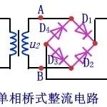
Have you ever wondered how your phone charger or laptop power supply can convert the 220V AC from the wall into the 5V or 3.3V DC that your devices need? Today, we will delve into the mysteries of AC-DC conversion, covering everything from the conversion principles to PCB design, packed with valuable insights!
Why Convert AC to DC?
Everyday appliances like mobile phones and routers typically require 5V or 3.3V DC voltage to operate, while household power supply is 220V AC, making this conversion essential.
So why don’t power stations transmit DC directly? Because electricity is often generated in remote areas or coastal regions, AC can be transmitted over long distances with reduced losses using a “high voltage, low current” method. Once it reaches urban areas, it is stepped down to 220V AC at substations before finally reaching our homes.
What Are the Two Methods of AC to DC Conversion?
1. Transformer Conversion
The principle involves three simple steps:
- First, a low-frequency transformer (suitable for 50-60Hz AC) converts high-voltage AC to low-voltage AC;
- Next, a rectifier circuit converts low-voltage AC to DC (as shown in the diagram below);
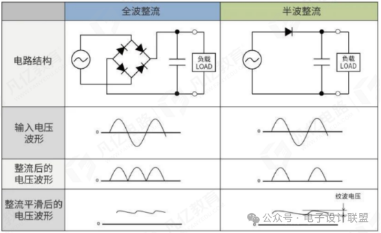
- Finally, a capacitor filter reduces the ripple in the DC output, smoothing the voltage.
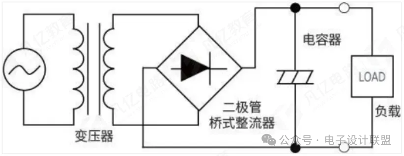
The circuit implementation can refer to the AC-DC transformer method shown above.
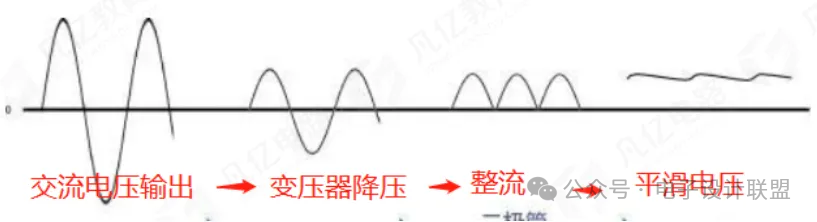
The waveform changes from AC input to DC output are shown in the diagram above, clearly illustrating the voltage conversion process.
2. Switching Mode Conversion:
This method involves more detailed steps:
- First, a bridge rectifier converts AC to DC;
- After smoothing the voltage with a capacitor, a switching element chops the DC;
- A high-frequency transformer steps down the voltage to a square wave;
- Rectification occurs with a diode for half-wave rectification, followed by smoothing with a capacitor, ultimately outputting DC.
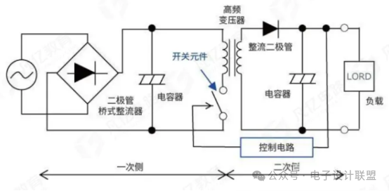
The circuit structure is shown in the diagram above, illustrating the AC-DC switching method.
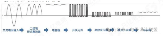
The waveform changes are shown in the diagram above, indicating a more efficient process.
Comparison of the Two Methods (with Pros and Cons)
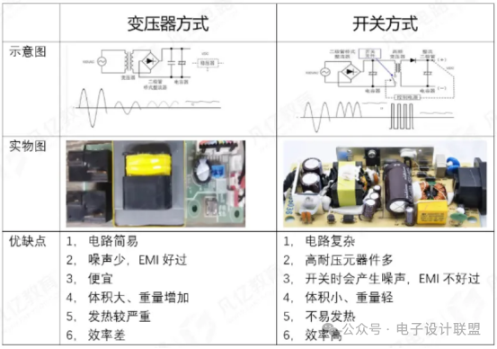
As shown in the diagram below, both conversion methods have their advantages and disadvantages:
- Transformer method: Simple circuit, low noise, low cost, but large size, heavy weight, significant heat generation, and low efficiency;
- Switching method: Small size, lightweight, high efficiency, but complex circuit, many high-voltage components, high noise during switching, and difficult EMI (electromagnetic interference) management.
 What Does a Complete AC-DC Circuit Look Like?
A reliable AC-DC circuit should include several core modules:
- Input filter circuit: Removes high-frequency noise to ensure stability in subsequent circuits;
- Rectifier bridge: Composed of 4 diodes, converting both positive and negative halves of AC to DC;
- Filter circuit: Uses capacitors or inductors for low-pass filtering to reduce ripple;
- Voltage regulation circuit: Adjusts output voltage through feedback using a voltage regulator;
- Output protection circuit: Prevents overcurrent, overvoltage, and short circuits to protect devices;
- Control circuit: Includes switch-mode power supply controllers, managing the entire circuit operation.
Practical Analysis: HFC0500 Chip Application Circuit
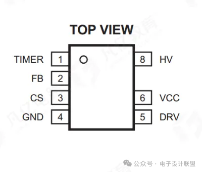
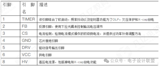
Using the HFC0500 chip as an example, let’s see how the actual circuit works:
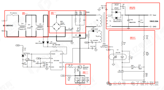
- The fuse provides current protection, the common mode inductor filters common mode interference, and the X capacitor CX1 eliminates differential mode interference;
- After rectification by the bridge rectifier, the capacitor further filters interference, and the RCD absorption circuit protects the switching tube;
- The chip’s pin 5 outputs a driving signal to control the chopping of the switching tube;
- The high-frequency transformer T1 steps down to a square wave, which is then half-wave rectified by diode D6;
- Capacitors C10 and C11 filter the output to the required voltage;
- The feedback section uses an optocoupler to isolate the feedback signal, achieving voltage regulation.
PCB Design Pitfalls Guide
To ensure effective PCB design for AC-DC, keep these points in mind:
- Minimize the three major loops: Input loop (C1-T1-Q1-R11/R12/R13-C1), auxiliary winding loop (T1-D4-R4-C3-T1), output loop (T1-D6-C10-T1). The smaller the loop, the stronger the anti-interference capability (refer to the top and bottom views in the diagram below);
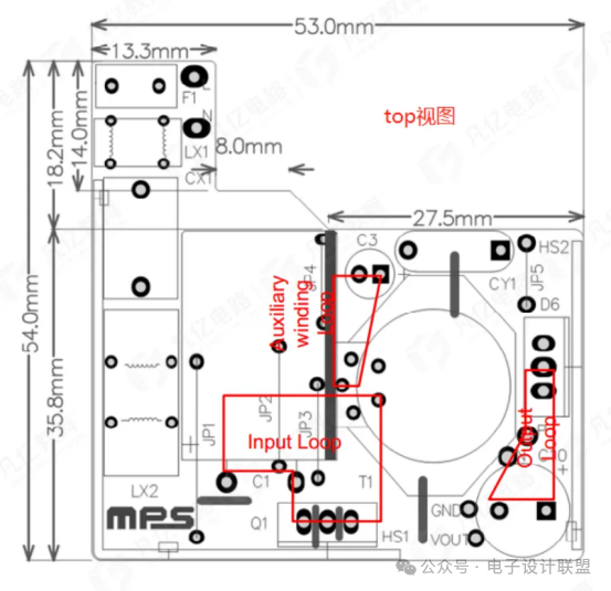
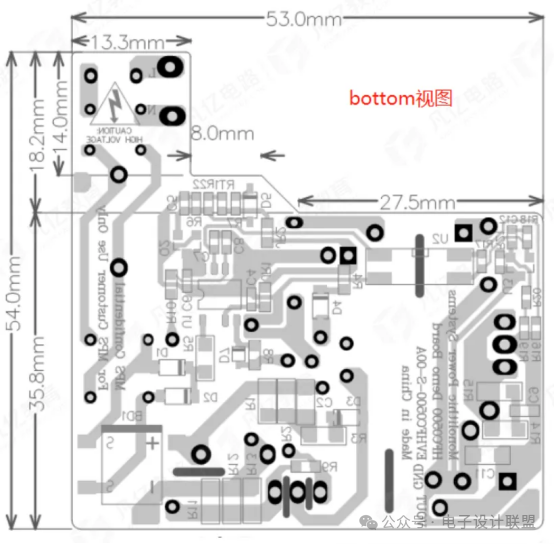
- Separate GND: Connect the input loop GND and control circuit GND only at C1;
- Isolate high-frequency interference: The heatsink of the switching tube Q1 connects to the main GND plane, and the surrounding circuit board can be hollowed out to isolate noise;
- Protect feedback lines: Keep them separate from power lines and minimize their length to avoid interference;
- Isolate the optocoupler: Hollow out the board frame in the middle of the optocoupler to isolate signals on both sides.
From power plants to chargers, AC-DC conversion is a crucial link in power applications. Mastering this knowledge not only helps you understand circuit principles but also allows you to avoid pitfalls in design. What other power-related knowledge would you like to learn? Let me know in the comments!
Is finishing the schematic enough? Senior engineers are quietly checking for these 8 hidden traps.
2025-11-20
What skills does a hardware engineer with a salary of 500,000 have that you don’t?
2025-11-19
Circuit design is simple; here are 10 classic circuit diagrams to share.
2025-11-18