
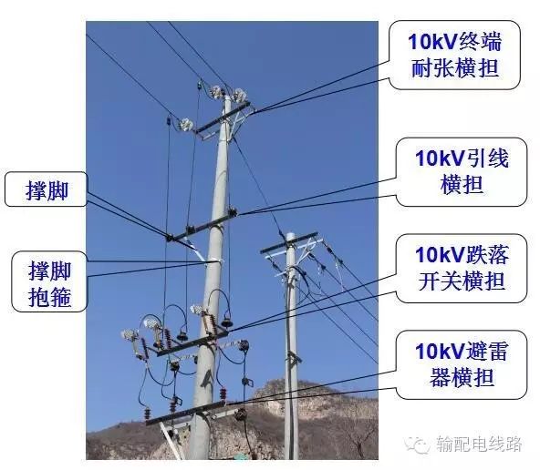
1Definition and Classification of Power Distribution Iron Accessories
Iron accessories are commonly referred to as components used in power transmission and transformation lines; they belong to non-standard hardware. The iron accessories in power distribution lines generally refer to the iron parts on concrete poles and their connections. This includes various clamps, pins, cross beams, isolation beams, tension rods, and wire rods, etc. It does not include power hardware, as most hardware is standardized.
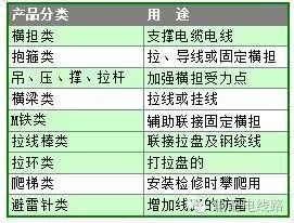
2Cross Arm
A cross arm is an angle iron fixed horizontally at the top of a power pole, which holds porcelain insulators and hardware; it is an important component of the pole tower, used to support conductors and lightning wires, ensuring they maintain a specified safety distance. Based on materials, it can be classified into iron cross arms, porcelain cross arms, and composite insulated cross arms. Based on usage, it can be divided into cross arms for lines of 10KV and below, such as single pole cross arms, door pole cross arms, lifting cross arms, and lead wire cross arms, as well as assembled cross arms for lines of 35KV and above (straight, corner, and tension) etc. The hardware used to assist in the installation of cross arms includes M iron, cross arm connecting plates, support legs, curved plates, clamps, single-headed bolts, double-headed bolts, and pins.
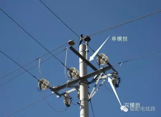
Straight cross arms are used to bear vertical loads and horizontal loads of conductors under normal conditions without line break; tension cross arms bear vertical and horizontal loads, as well as the pulling force difference of conductors; corner cross arms bear vertical and horizontal loads while also withstanding significant unilateral pulling force of conductors. Based on the stress situation of the cross arms, single cross arms are used for straight poles or corner poles under 15 degrees, while double cross arms are used for corner poles between 15 and 45 degrees, tension poles, terminal poles, and branch poles. For corner poles over 45 degrees, tension poles, terminal poles, and branch poles, cross arms are used. (In some regions, double cross arms are used for all poles.) Cross arms are generally installed 200mm from the top of the pole; straight cross arms should be installed on the power side, while corner poles, terminal poles, and branch poles’ cross arms should be installed on the tension side.
2.1 Single Pole Cross Arm
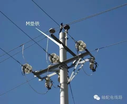
The main raw material is equilateral angle steel, and the specifications are named according to the size of the angle steel and the length of the cross arm, such as: ∠63×6×1800. It is used for the installation of single poles for power transmission lines of 10kV and below, and is categorized into single cross arms and double cross arms based on installation. A single pole single cross arm mainly consists of a cross arm, U-shaped clamp, and M pad iron (some poles also have support legs and clamps for support legs); a single pole double cross arm mainly consists of a cross arm, double-headed bolts, and M pad iron.
2.2 Door Pole Cross Arm
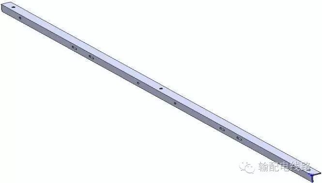
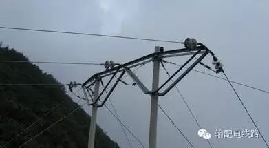
Door pole cross arms, the main raw material is equilateral angle steel, and the specifications are named according to the size of the angle steel and length, such as: ∠90×8×5000. It is used for the installation of door poles for power transmission lines of 10kV and below, and the specifications and processing vary according to the differences in the root openings.
2.3 Lifting Cross Arm
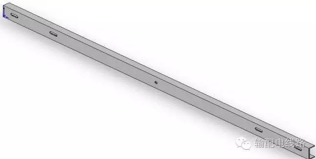
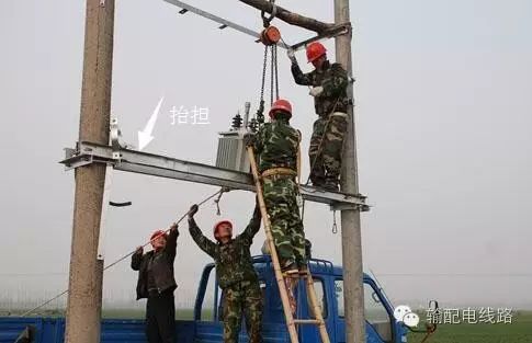
The lifting cross arm, mainly made of channel steel, is the lifting beam cross arm for transformers and vacuum switches, installed above the lifting clamp, and its specifications are represented by the size and length of the channel steel used, such as [10×3200.
2.4 Assembled Cross Arm
The assembled cross arm includes ground wire cross arms (concrete ground cross arms, angle steel ground cross arms, and channel steel ground cross arms) and conductor cross arms (straight pole cross arms, corner pole cross arms, and tension cross arms). There are two assembly methods for angle steel ground cross arms, one resembling the shape of conductor cross arms, and the other with angle steel inverted, opposite to the installation method of the main material angle steel of conductor cross arms. It is used in projects of 35KV and above, with specifications indicated by the pole type used, i.e., straight pole specifications include the capital letter “Z” in English, such as HZM-2, while corner pole specifications include “J”, such as: J1, etc. The main raw materials for angle steel ground cross arms and conductor cross arms are angle steel and flat iron, while channel steel ground cross arms mainly consist of channel steel, round steel, and steel plates.
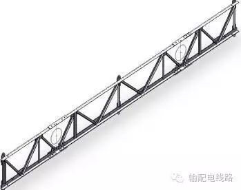 Angle Steel Ground Cross Arm
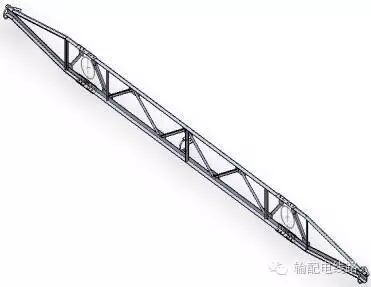
Straight Cross Arm
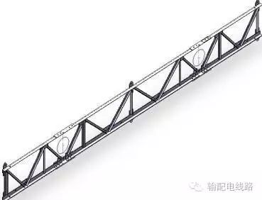
Corner (Tension) Cross Arm
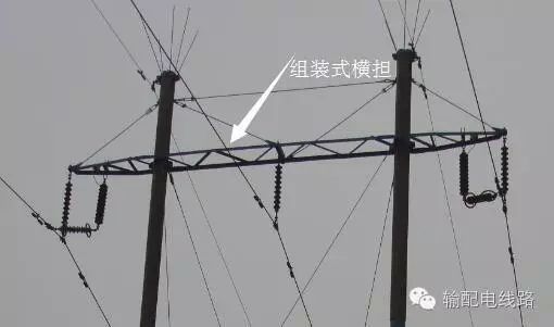
2.5 Other Cross Arms
In addition to the cross arms mentioned above, there are other cross arms, such as commonly referred to as drop insurance cross arms, knife switch cross arms, link cross arms, lead wire cross arms, incoming and outgoing line cross arms, and lightning rod cross arms, mainly used in projects of 10KV and below. The specifications are expressed based on the specifications of the angle steel used.
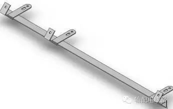
Drop Insurance Cross Arm
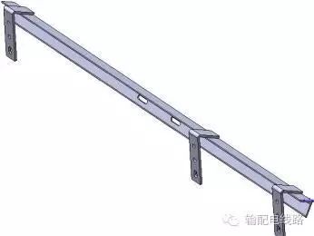
Knife Switch Cross Arm
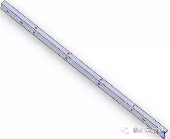
Lead Wire Cross Arm
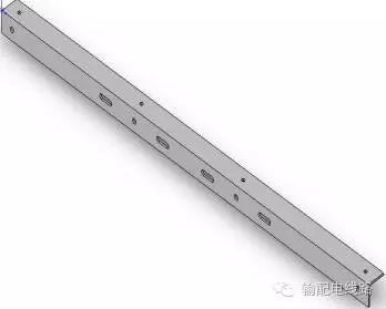
Lightning Rod Cross Arm
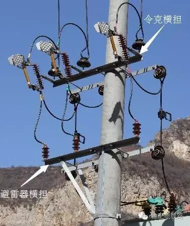
2.6 Components for Assisting Cross Arm Installation
Components assisting in cross arm installation include M iron, five-eye connecting plates, curved plates, support legs, bolts, etc.
The five-eye connecting plate, also known as the five-hole pulling plate or double cross arm connecting plate, has five holes on its surface as the name suggests. It is generally used in 10KV and below overhead line transfer and terminal poles, connecting the porcelain bottle holes of the two cross arms at corners and tension single poles, serving to connect the double cross arms, achieving the function of fixing and installing standard hardware. The center distance of the two holes on the connecting plate varies according to the size of the installed pole, and the length also varies with the change in the center distance of the two holes. The specification expression for the five-eye connecting plate is -B×b×l, such as -60×6×470;
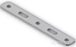
Flat Steel Type
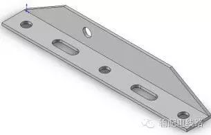 Angle Steel Type
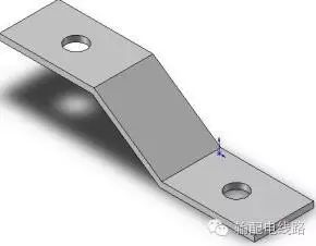
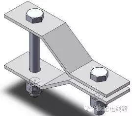
Curved plates, also known as iron curved plates or Z-shaped iron, usually come in sets of two, and their specifications are indicated according to the specifications of the flat iron used, such as -40×4×250.
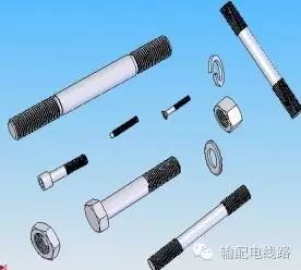
Bolts include double-headed bolts, single-headed bolts, and pins. Double-headed bolts, also known as double-headed screws, are bolts with threads on both ends, used to connect two components that are a distance apart, generally with two nuts on each end. Their specifications are Md×l, such as M16×250; single-headed bolts generally have one nut, while pins generally have double nuts and double washers.
Support legs can be categorized into single supports, V supports, and L supports. Single supports come in several types, including flat iron type, flattened, and angled. V supports, also known as Yuanbao supports, are used to enhance the load-bearing of cross arms in lines of 10KV and below. Single supports require support leg clamps for installation.
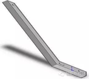
L Support
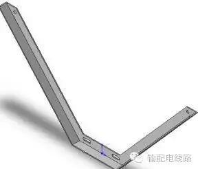 V Support
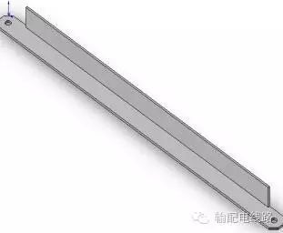 Single Support (Angled)
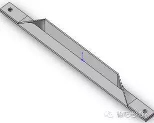
Single Support (Flattened)
3Clamp
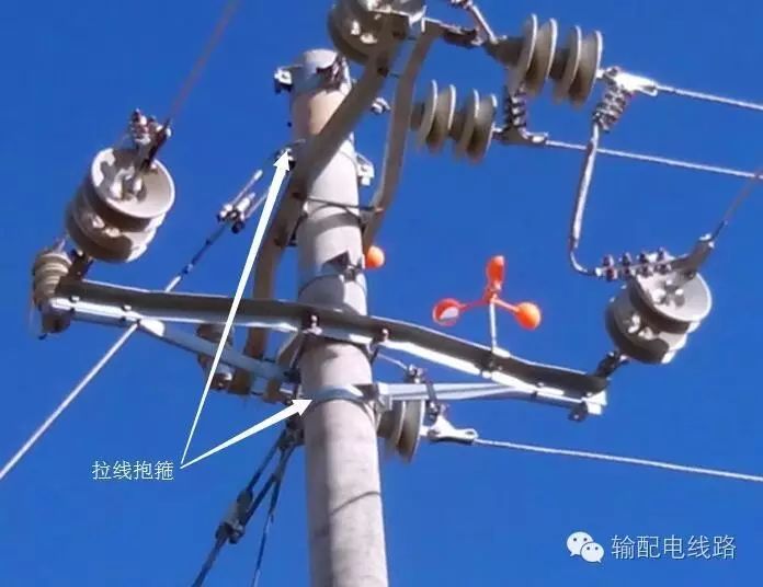
The so-called clamp is a component that holds or clamps another material with a certain material. It belongs to fasteners. The clamp device consists of a clamping plate, wing plate, connecting rib plate, bolts, and inner lining pad. There are many types of clamps, such as pole top support clamps, cable clamps, cross arm clamps, and tension clamps. Generally, the left and right halves of the clamp are joined together, both halves are semi-circular, and the ends of the semi-circular rings curve outward, each forming a mounting ear with a bolt connection hole, connected and installed using a necked bolt, and the main raw material is flat steel.
3.1 Pole Top Support Clamp
The pole top support clamp is installed at the top of the pole and is divided into single top single clamp, double top single clamp, single top double clamp, and double top double clamp, used for lines of 10KV and below.
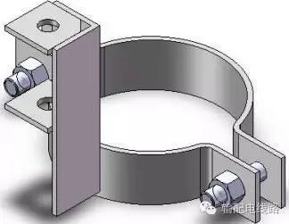
Single Top Single Clamp
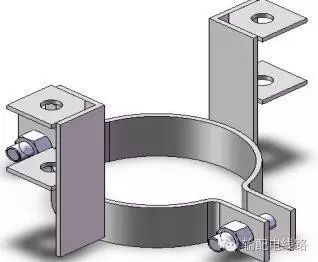
Double Top Single Clamp
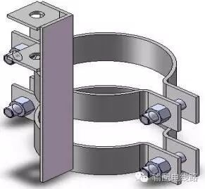
Single Top Double Clamp
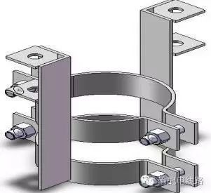
Double Top Double Clamp
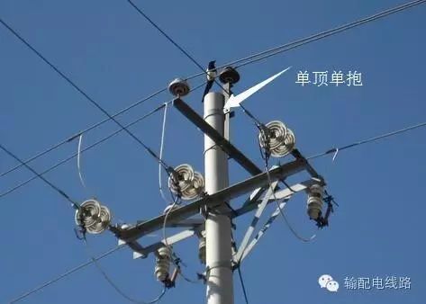
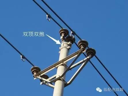
3.2 Tension Clamp
The tension clamp is used in the line to fix the pole with a tension wire, including flat clamps, reinforced flat clamps, double tension clamps, and four tension clamps. The specifications are generally indicated by the flat steel specifications and the diameter of the pole being clamped, such as: -60×6×150.
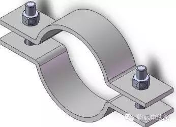
Flat Clamp
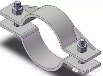
Reinforced Flat Clamp
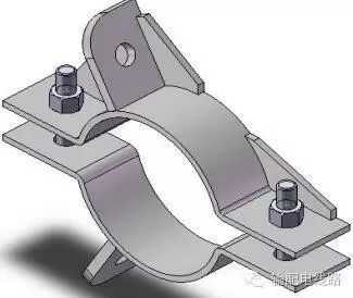
Double Tension Clamp
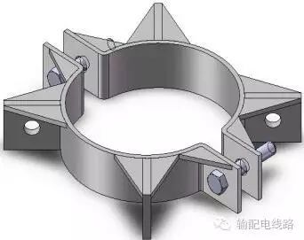
Four Tension Clamp
3.3 Conductor Clamp
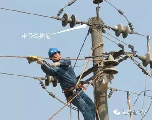
Conductor clamps are divided into conductor clamps and conductor tension clamps, used for hanging wires, conductors, tension wires, or both conductors and tension wires in power lines. They are used in projects of 110KV and below, and their specifications are indicated by the numbering system designed by various designs.
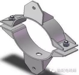
Hanging Wire Clamp
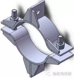
Middle Conductor Clamp
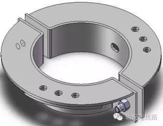
Three-Pole Conductor Clamp
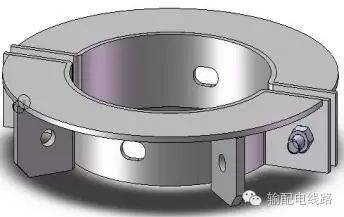
Three-Pole Conducting Tension Clamp
3.4 Support and Tension Clamps
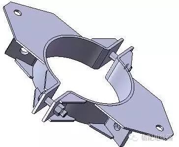
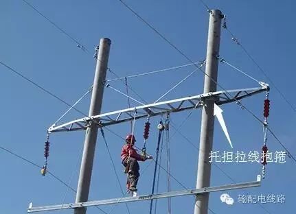
Support and tension clamps are used in power lines of 35KV and above for supporting horizontal arms or simultaneously supporting horizontal arms and tension wires. The difference between the two is that the latter has more tension plates than the former, and their specifications are indicated by the numbering system designed by various designs, such as: ④ clamp, etc.
3.5 Lifting Clamp
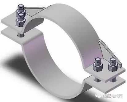
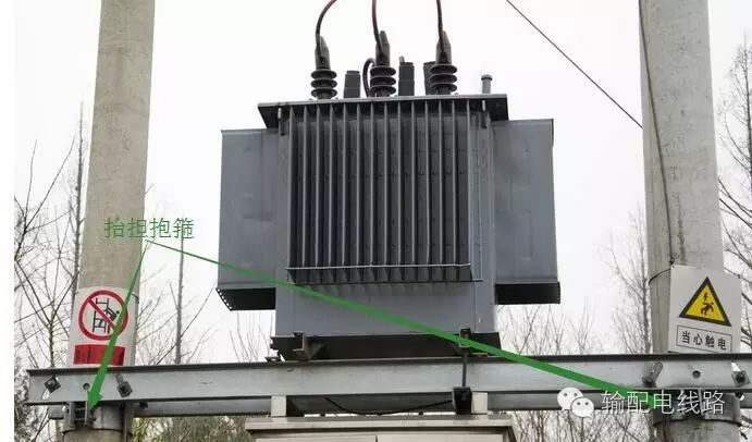
The lifting clamp, also known as lifting support, is used for the lifting clamp of the lifting cross arm, with two connection screw holes on one side of the mounting ear, generally using four sets of necked bolts for connection. Its specifications are indicated by the flat steel specifications used and the diameter of the pole being clamped, such as -80×8×280.
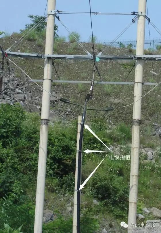
3.6 Cable Clamp
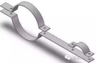
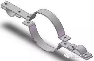
The cable clamp is used for fixing cables when they are mounted on poles, and it is divided into single cable clamps, double cable clamps, and multi-cable clamps according to the number of fixed cables, with the main difference being the quantity of cable clamps. Their specifications are indicated by the specifications of the materials used and the diameter of the poles being clamped, such as -60×6×320.
Single Cable Clamp
 Double Cable Clamp
3.7 Support Leg Clamp
The support leg clamp is used for installing support legs in projects of 10KV and below, generally available in several types including welded plates, welded bolts, and flat clamps. Its specifications are indicated by the specifications of the raw materials used and the diameter of the poles being clamped, such as -60×6×210.
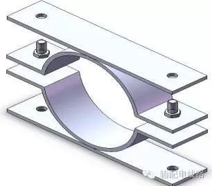
Support Leg Clamp (Welded Plate)
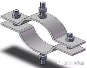
Support Leg Clamp (Welded Bolt)
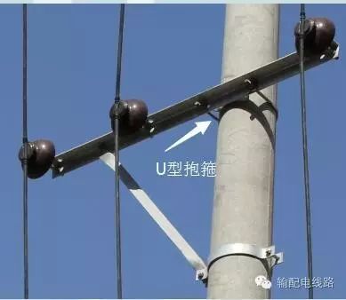
3.8 U-Shaped Clamp
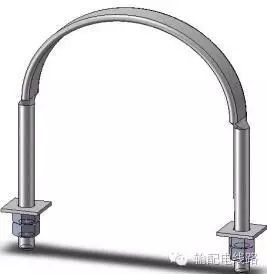
The U-shaped clamp, also known as round steel clamp, is made of round steel and is used for connecting single angle steel components with round rods. Each set generally includes 4 nuts and 2 square pads. Its specifications are indicated by the specifications of the round steel used and the diameter of the poles being clamped. The specification expression is: Φd×D, such as Φ16×250.
4Suspension, Compression, Support, Tension Rods
Suspension, compression, support, and tension rods are used to support load-bearing rods. The iron accessories assisting these rods’ installation include section plates, adjustment bolts, bolts, pins, and eye bolts.
4.1 Suspension Rod
Suspension rods are classified into round steel suspension rods for power lines of 10KV and below, adjustable round steel suspension rods for projects of 35KV and above, and angle steel suspension materials for other areas. The adjustable round steel suspension rods have three-eye connecting plates made of angle steel and steel plate, and their specifications are indicated by the size of the round steel or the applicable pole type, such as: DG18-4.
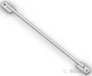
Round Steel Suspension Rod
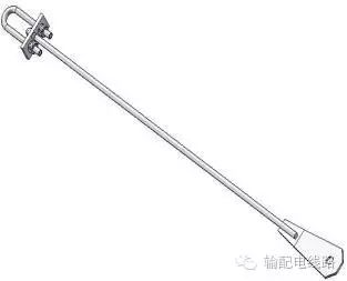
Adjustable Round Steel Suspension Rod
4.2 Compression Rod
Compression rods are used to strengthen the load points of cross arms. When corner tension double poles bear upward pulling loads and cross arms and hanging line hardware cannot balance, compression rods replace the original suspension rods. Compression rods are generally divided into left and right compression rods, and their specifications are indicated by the angle steel specifications used, such as: ∠63×6×1540.
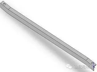
4.3 Support Rod
Support rods are generally used for ground wire cross arms, referred to as ground support rods, typically consisting of 8 rods in a set, divided into left and right, and their specifications are the same as those of compression rods.
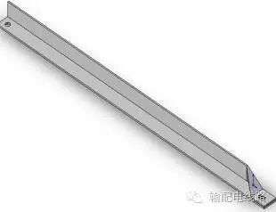
4.4 Tension Rod
Tension rods are generally used in lines of 35KV and above, serving to stabilize the load on poles and cross arms. They are generally divided into horizontal tension rods and diagonal tension rods. Horizontal tension rods have several installation methods, including installation using eye bolts, installation using four-eye section plates, and direct insertion into poles. Typically, straight poles use eye bolts or direct insertion, while tension poles use four-eye section plates for installation. Their specifications are indicated by the size of the round steel and the type of tension rod, such as: LG16-3, XLG20-1.
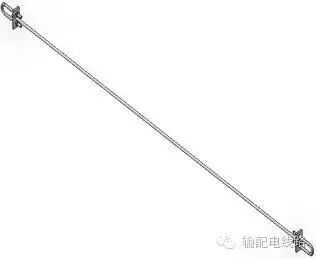
Horizontal Tension Rod
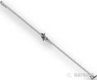 Diagonal Tension Rod
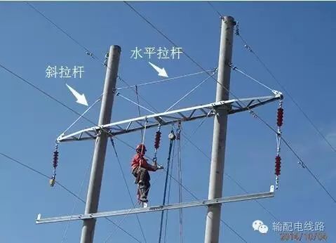
4.5 Other Auxiliary Components for Installing Suspension and Tension Rods
Auxiliary components include section plates (two-eye, three-eye, and four-eye), bolts, pins, eye bolts, etc.
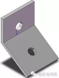
Two-Eye Section Plate
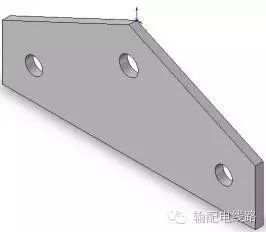
Three-Eye Section Plate
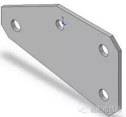
Four-Eye Section Plate
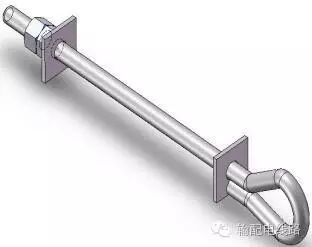 Eye Bolt
5Cross Beam
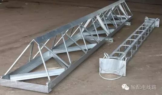
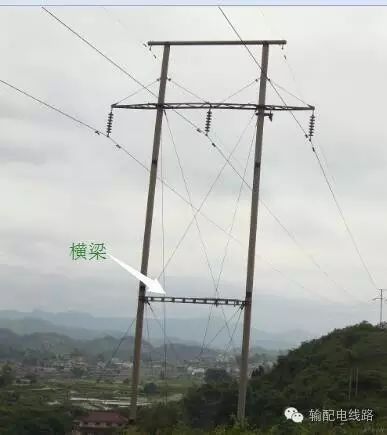
A cross beam is a hardware component that is placed between two vertical columns. Based on usage, it can be divided into height-increasing angle steel cross beams and hanging wire steel cross beams. Composed of main material angle steel, belly material steel plate, round steel, connection bolts, and U clamps. In projects of 35KV and above, generally, if the height of a single side of the door pole exceeds 18 meters, a height-increasing angle steel cross beam must be used to enhance the stability of the pole, installed using U clamps. Hanging wire steel cross beams are used in substations, mainly for hanging wires, with specifications such as GL-1.
6M Pad Iron
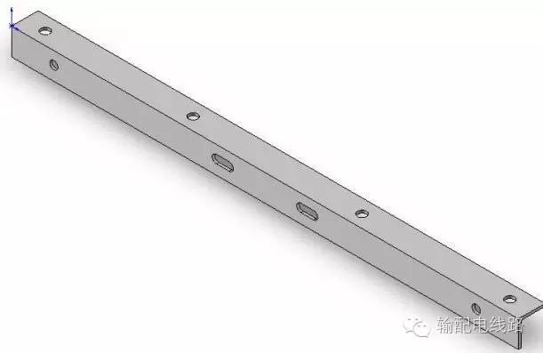
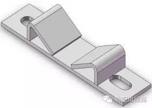
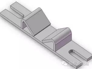
The M-type pad iron is used to assist the connection of angle steel cross arms with poles. The role of M-type pad iron is simple: without it, the cross arm would slip and distort under load, mainly serving a fixed function, with some directly welded with two small angle steels on the cross arm. The main material of M-type pad iron is flat iron, and its specifications are determined by the installation pole position. To increase the installation range of M iron, its double-headed bolt holes are processed into 40 long slot holes (kidney holes). The model specification expression is: -a×b×D, such as -60×6×190.
7Tension Rod
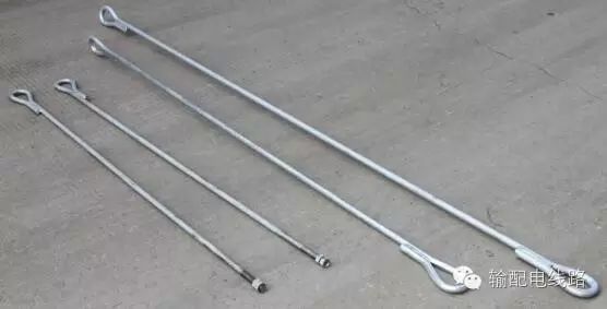
A tension rod is a non-standard hardware component for connecting tension wires to ground anchors or other metal parts. It is classified into single-bend tension rods and double-bend tension rods based on appearance. Its main function is to connect tension reels and steel strands to stabilize poles. Single-bend tension rods have one end threaded, while double-bend tension rods are divided into 90° and 180° (referring to the angle of the bend of the tension wire). Their specifications are indicated by the diameter of the round steel and the length after shaping, such as: Φ25×2700.
8Tension Ring
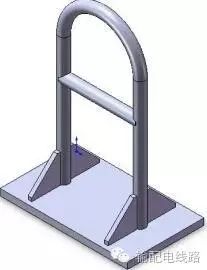
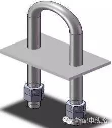
A tension ring is used for processing tension reels or connecting tension reels, divided into split tension rings and assembled tension rings. Specifications are named according to the round steel used for the tension ring, such as Φ28.
Assembled Tension Ring
 Split Tension Ring
9Ladder
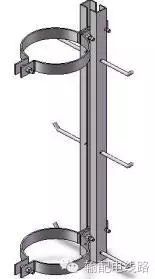
A ladder is a metal component installed on poles or other maintenance locations for easy installation and maintenance. It is mainly used for the installation and maintenance of large tension poles, power plants, substations, converter stations, and switch stations. It is divided into flat steel ladders, angle steel ladders, steel pipe ladders, and channel steel ladders. Composed of ladder main material, foot nails, connecting components, and connecting bolts.
The specifications of large tension pole ladders are indicated by the pole specifications, such as Φ310×18M; while the specifications of flat steel and angle steel ladders are indicated by design naming, such as P-1, E-1, etc.
10Lightning Rod
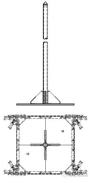
A lightning rod is a grounding metal rod system installed vertically at the top of the protected body or around the protected area to prevent lightning strikes. It intercepts lightning strikes with the tip of the metal rod to prevent them from falling on objects within the lightning rod’s protection range, gradually neutralizing the electricity carried by the clouds and the ground through down conductors and grounding devices, thus preventing accidents.
11Ground Wire
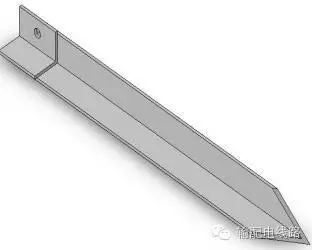
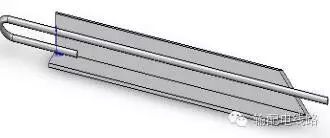
Ground wire connects lightning protection facilities in power lines and substations, serving to divert lightning current. Based on processing materials, it is divided into ground flat iron, ground angle steel, and ground round steel; ground flat iron is further divided into punched and non-punched types, ground angle steel is divided into punched, reinforced, and welded types, and ground round steel is divided into non-welded, welded single plate, and welded double plate types.
Ground Angle Steel (Reinforced Type)
Ground Angle Steel (Welded Type)
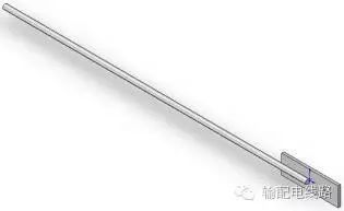
Ground Round Steel (Single Plate)
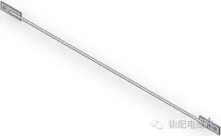
Ground Round Steel (Double Plate)
12Anchor Bolt
Used for the foundation of iron towers or other foundations that need to be embedded for the installation of the above-ground part. Its processing methods vary based on usage and geological conditions, including welded round steel, welded plates, angle welding, etc. Their specifications are indicated by the specifications of the round steel used. Generally, if there are no special requirements, a set of anchor bolts refers to one bolt without including stirrups.
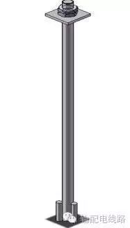
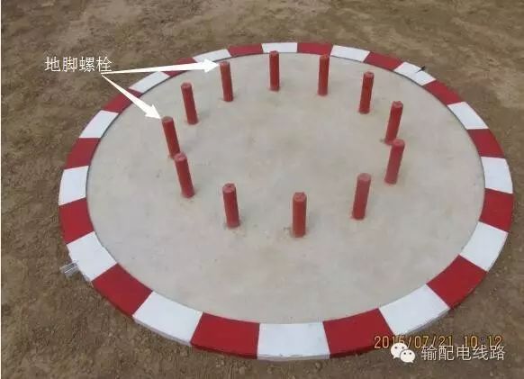
13Other Iron Accessories
In addition to the above iron accessories, there are also door-type iron, lightning rod brackets, T-shaped iron, Z-shaped brackets, T-shaped iron, seven-shaped iron, triangular brackets, pointed iron, etc.
13.1 Door-Type Iron
Door-type iron, also known as door-type frame, is used inside low-voltage civil lines, with footboards fixed with expansion bolts. It is divided into two-eye door-type iron and four-eye door-type iron based on the number of hanging wires.
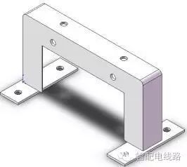
Two-Eye Door-Type Iron
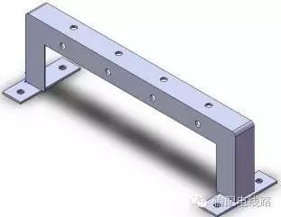 Four-Eye Door-Type Iron
13.2 Lightning Rod Bracket
The lightning rod bracket is used for installing lightning rods and comes in T-shaped, flat steel, and angle steel types.
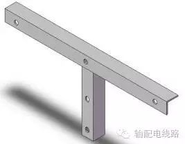
Angle Steel (T-shaped)
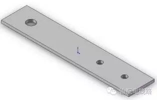 Flat Iron Type
13.3 Other Iron Accessories
Other iron accessories include T-shaped iron, Z-shaped brackets, T-shaped iron, seven-shaped iron, triangular brackets, pointed iron, cable hooks, etc. T-shaped iron and seven-shaped iron are available in two-eye and four-eye types, while triangular brackets are available in standard and tension types.
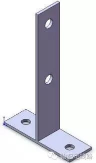
T-shaped Iron
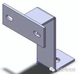 Z-shaped Bracket
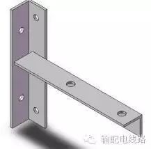
Two-Eye T-shaped Iron
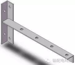 Four-Eye T-shaped Iron
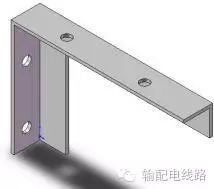
Two-Eye Seven-shaped Iron
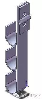
Four-Eye Seven-shaped Iron
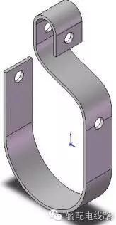 Single Cable Ditch
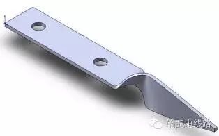 Two-Eye Pointed Iron
Dance Out a Wonderful LifeWe in Power Transmission LinesBasic Knowledge Platform The Most Professional Power Transmission and Distribution Lines WeChat ID: shudianxianlu Public Account: Power Transmission and Distribution Lines
Design General Group: 72468968
Electrical General Group: 246684395
Structure General Group: 67469156
Construction General Group: 46092726
Operation and Maintenance General Group: 490808577
Power Cable Group: 79261260
Cooperation Email: [email protected]
The public account is established by many technical enthusiasts in power transmission and distribution lines, and everyone is welcome to share relevant technical knowledge. Some works come from the Internet, and the authenticity of the source cannot be verified. If there are copyright issues, please contact us directly for deletion.
Click the upper right corner to share this article, or click“View Public Account” to follow this WeChat.