1. ULINK2 Emulator
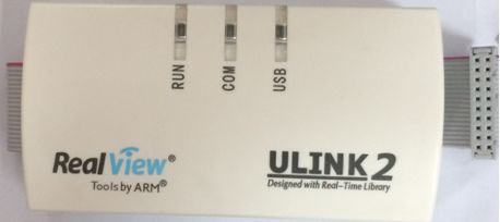
ULINK2 is the latest emulator from ARM designed for use with RealView MDK. It is an upgraded version of the ULINK emulator. ULINK2 not only has all the features of the ULINK emulator but also adds support for Serial Wire Debug (SWD), return clock support, and real-time agents. Development engineers can easily perform on-chip debugging (using on-chip JTAG, SWD, and OCDS) and Flash programming on target hardware by combining the RealView MDK debugger with ULINK2.
New Features of ULINK2
Standard Windows USB driver supports plug-and-play for ULINK2
Supports Serial Debugging based on ARM Cortex-M0,3,4
Supports memory read/write, terminal emulation, and serial debug output during program execution
Supports 10-pin connection cable (also supports 20-pin connection cable)
Main Functions of ULINK2:
USB communication interface for high-speed downloading of user code
View storage areas/registers
Fast single-step program execution
Multiple program breakpoints
On-chip Flash programming
Technical Specifications of ULINK2
Feature
ULINK2
RAM Breakpoints
Unlimited
ROM Breakpoints (ARM7/9)
2 max
ROM Breakpoints (Cortex-M3)
8 max
ROM Breakpoints (μPSD)(Cannot Set While Executing)
5 max
ROM Breakpoints (XC800)
(Cannot Set While Executing)
4 max
ROM Breakpoints (XC166)
4 max
Execution Breakpoints (Set While Executing)
√
Access Breakpoints (ARM7/9)
2 max
(R/W Only, With Value)
Access Breakpoints (Cortex-M3)
4 max
(With value)
Access Breakpoints (μPSD)
3 max
Access Breakpoints (XC800)
1 in IDATA max
Access Breakpoints (XC166)
1 max
Real-Time Agent (ARM7/9)
√
Serial Wire Debug (Cortex-M)
√
Data Trace (Cortex-M3)(Serial Wire Viewer)
√
JTAG Clock
<= 10MHz
Memory R/W
≈ 28KB/s
Flash R/W
≈ 25KB/s
Data Trace Streaming
1Mb/s
10-pin (0.05″)
(Cortex Debug Connector)
√
20-pin (0.1″ (ARM Standard JTAG Connector)
√
16-pin (0.1″ (Infineon OCDS Connector)
√
14-pin (0.1″ (ST μPSD Connector)
√
I/O Voltage Range
2.7V – 5.5V
XC800 (8051)
√
μPSD (8051)
√
XC166/XE166/XC2000
√
LPC950 (8051)
√
ARM7
√
ARM9
√
Cortex-M0
√
Cortex-M1
√
Cortex-M3
√
Cortex-M4
√
2. Installation and Usage of ULINK
1. Please ensure that the ULINK driver is correctly installed; otherwise, the ULINK emulator cannot be used.
2. Project Setup
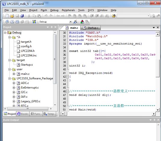
Open a project file as shown below
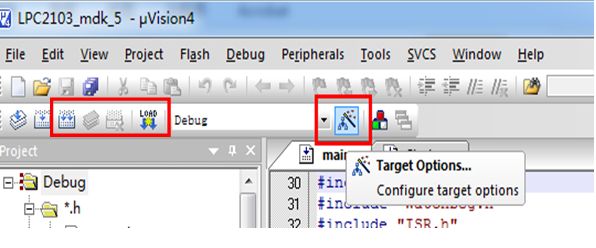
Click the project settings icon as shown
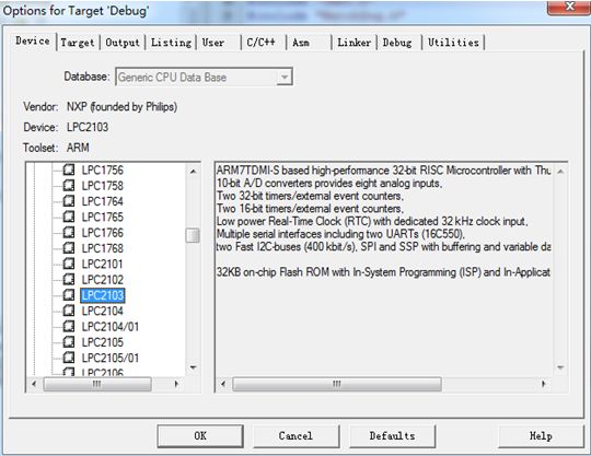
Open the project settings page, select chip model: LPC2103
Set the Debug selection card as follows: select hardware emulation on the right and choose Ulink Arm Debug as the emulator
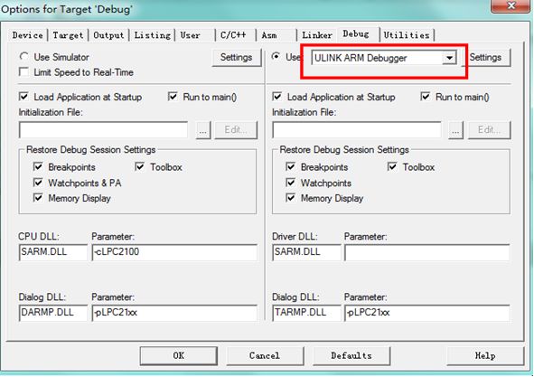
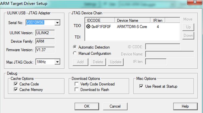
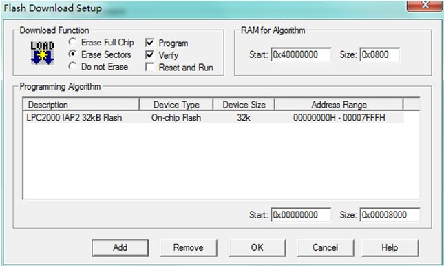
Open settings and set as follows:
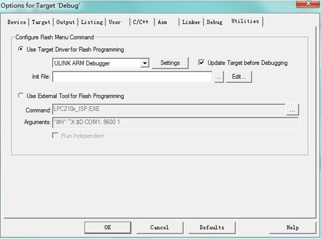
Set the Utilities tab
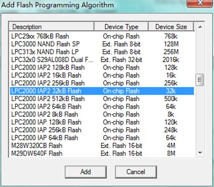
In Settings, first set the download option, then click Add to add the programming algorithm
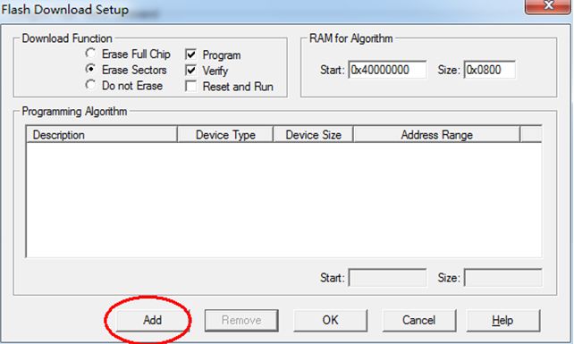
The internal flash of the LPC2103 chip is 32K, so select the following option
Then click OK to complete the setup
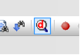
3. Start Debugging
Now you can start debugging by clicking the Debug shortcut icon
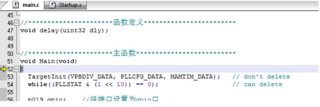
Enter the emulation interface as shown below
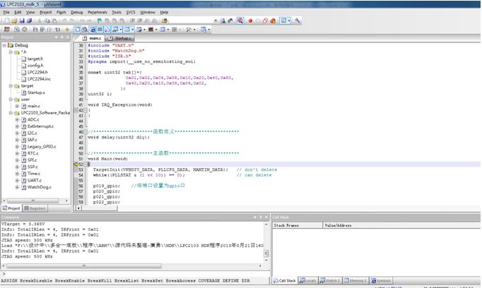
We can see the emulation toolbar

We can see that the program running progress is just an arrow
Thus, the ULINK and ARM7 core board are successfully connected, and you can now perform single-step, full-speed running, and other debugging.