1 Preparation Before Debugging
This section introduces a method to achieve serial debugging of user programs for the 51 microcontroller using the software simulation feature of Keil. This method requires no hardware emulator, and even no user circuit board is needed. All that is required is:
① Hardware. A standard computer (which needs to have 2 standard serial ports) and a serial cable (both ends are female, connected as shown in Figure 1).
② Serial port software can be a custom debugging or communication software developed by the user, or a general-purpose serial port software (such as Serial Assistant, Serial Debugger, etc.), mainly used for data transmission and reception. If there is no suitable serial debugging software, a free serial tool called TurboCom developed by the author can be used.
2 Introduction to Basic Debugging Commands
This serial debugging method mainly utilizes the powerful software simulation capabilities of Keil. In the newer versions (above 6.0) of Keil software, the simulation capabilities have been enhanced, allowing more microcontroller functions to be simulated using software. Among these functions, a very important one is using the computer’s serial port to simulate the microcontroller’s serial port (which is different from the excitation file method used by many software during simulation, as it can communicate directly with other serial ports, making it more convenient and flexible). First, we need to introduce two commands that are required during simulation: ASSIGN and MODE.
2.1 ASSIGN Command
This command binds the microcontroller’s serial port to the computer’s serial port. The basic usage is:
ASSIGN channeloutreg
Where: channel represents the computer’s serial port, which can be COM1, COM2, COM3, or COM4; inreg and outreg represent the microcontroller’s serial port. For a common microcontroller with only one serial port, they are SIN and SOUT; for microcontrollers with two or more serial ports, they are SnIN and SnOUT (n=0,1,…, which is the serial port number of the microcontroller).
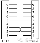
Figure 1 Serial Connection Diagram
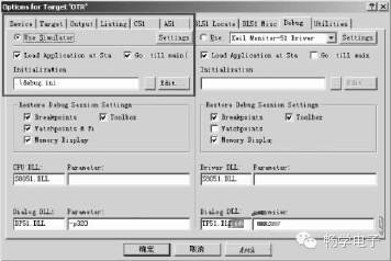
Figure 2 Simulation Parameter Settings
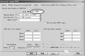
Figure 3 Crystal Oscillator Parameter Settings
 Enter Debug (Simulation Debugging) mode, and in the Output window’s command text box (usually in the lower left corner), enter the commands introduced above.
For example, to set the computer’s serial port 1 to the microcontroller’s serial port:
For instance:
ASSIGN COM1SOUT
This binds the computer’s serial port 1 to the microcontroller’s serial port (for microcontrollers with only one serial port).
ASSIGN COM2S0OUT
This binds the computer’s serial port 2 to the microcontroller’s serial port 0 (for microcontrollers with multiple serial ports, pay attention to the position of the serial port number).
It is important to note that the parentheses for the parameters cannot be omitted, while outreg does not have parentheses.
2.2 MODE Command
This command sets the parameters for the bound computer serial port. The basic usage is:
MODE COMx baudrate, parity, databits, stopbits
Where: COMx (x = 1, 2, …) represents the computer’s serial port number; baudrate represents the baud rate of the serial port; parity represents the parity method; databits represents the data bit length; stopbits represents the stop bit length.
For example:
MODE COM1 9600, n, 8, 1
This sets serial port 1 with a baud rate of 9600, no parity, 8 data bits, and 1 stop bit.
MODE COM2 19200, 1, 8, 1
This sets serial port 2 with a baud rate of 19200, odd parity, 8 data bits, and 1 stop bit.
Using these two commands, the computer’s serial port can be simulated as the microcontroller’s serial port. During software simulation, all data sent to the bound computer’s serial port will be forwarded to the Keil simulated microcontroller’s serial port, and the user program can receive this data through interrupt handling or polling; similarly, data sent to the microcontroller’s serial port will be sent out through the bound computer’s serial port, which can be received by other software. Utilizing this feature allows for easy simulation and debugging of the microcontroller’s serial port program. It is important to note that these two commands need to be used together.
2.3 Simulation Steps
First, connect the two serial ports of the computer together (or the two serial ports on two computers). One of these serial ports is used to simulate the microcontroller’s serial port, while the other is used for the debugging program. This allocation is up to the user, with no special requirements.
Secondly, write the user program and compile it successfully.
Then, set the relevant parameters in the project file (Project), as shown in Figures 2 and 3. The main settings are to choose the software simulation mode (Use Simulator) and the crystal oscillator parameters.
To avoid having to enter the serial port parameter setting commands every time you enter simulation mode, an initialization file can be created. The initialization file is a regular text file, and the content consists of the commands needed during simulation, entered one per line in order. As shown in Figure 2, a debug.ini initialization file has been created. Thus, each time you enter simulation debugging mode, Keil will automatically load the contents of debug.ini for initialization.
To correctly simulate the serial port, during software simulation debugging, the actual crystal oscillator frequency used in the user’s Keil project file properties also needs to be set. This parameter is very important as it directly affects the communication baud rate and can be set according to the actual parameters used. Note that the unit for this parameter is MHz.
Once the parameters are set, simulation can proceed. Click the icon on the toolbar.
mode com1 9600,0,8,1
assign com1Sout
Then set breakpoints, usually at critical places or where associated with the serial port. Click the icon to run (Run) the user program to make the user program operate (otherwise, no serial data can be received). At this point, use the serial debugging software or user debugging software to send communication commands or data packets, checking if the user program hits the breakpoints and whether the related variables are correct. You can also intentionally send data packets with erroneous data to observe whether the user program’s exception handling part is functioning correctly. If any errors in the program are found, you can immediately stop the simulation debugging, modify the code, and then repeat the above steps for simulation. Since there is no need to connect to the user’s target board or download the code to the user board, the speed is very high. All these steps are basically the same as using a hardware emulator, except that software simulation is used now.
It is important to note that during simulation, the actual baud rate of the microcontroller’s serial port is specified by the MODE command, and the parameters in the microcontroller program such as TMOD, SCON, etc., do not affect the serial port simulation state (meaning these parameters do not affect the simulation baud rate, even if they are incorrect). However, the enable bits for interrupts (such as ES, EA, etc.) still take effect; if ES or EA is disabled, then the serial port interrupt will not be entered.
Because this method uses the computer’s serial port to simulate the microcontroller’s serial port, and the simulation is conducted through the Keil software to convert the data on the serial port, rather than directly forwarding the data, the processing speed during actual simulation may be slightly lower than when the microcontroller is running. For example, in simulation mode, it might only send/receive 10 data frames in 1 second, while on the microcontroller hardware, it might send/receive 50 data frames in the same time. This is related to the speed of the computer used, but it does not affect the simulation.
For microcontrollers with multiple serial ports, theoretically, multiple serial ports can be bound at once, as long as the computer has enough serial ports. Generally, the number of serial ports needed on the computer using this method is twice the number of serial ports bound to the microcontroller. One serial port is occupied by Keil for simulating the microcontroller’s serial port; another serial port is occupied by the computer for sending and receiving data to and from the microcontroller’s serial port.
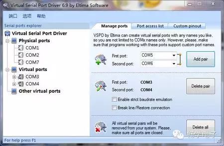
2.4 Hardware Serial Ports on the Computer Can Also Be Simulated with Software
In contrast, software-simulated serial ports automatically associate the serial ports in pairs, which can solve the problem of insufficient hardware serial ports on the computer and eliminate the need for wiring between serial ports. The downside is that the CPU load on the computer increases, and the real-time performance may not meet fast communication rates, potentially leading to data loss. As shown in the figure below.