Recently, I have been quite busy with work, but I still managed to squeeze out some time to finish the matrix LED clock mentioned in my last article. I made a video to introduce this clock, which you can watch on Bilibili or YouTube. Today, I am writing another article to detail the design concept and the production process, hoping to help everyone and that you will like it.
BGM:Lifeline
So I took my friends’ suggestions and started designing a new desktop clock. For the screen, I carefully considered: Large OLED screens are too expensive—PASS! Small OLED screens have poor display quality—PASS! Regular LCD screens are too ugly—PASS! Neon tubes are expensive and complicated to drive—PASS! E-ink screens have ghosting due to updates per second—PASS! Finally, I focused on something I used to play with in college—a dot matrix LED screen. First of all, this thing is very cheap, costing just over 1 yuan each, and using six can completely display the time for only 8 yuan. Adding a driver chip totals less than 20 yuan. Moreover, this display has a hardcore retro vibe, making it very suitable as a clock display.
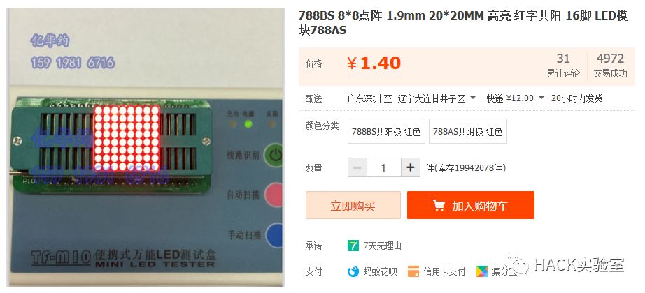
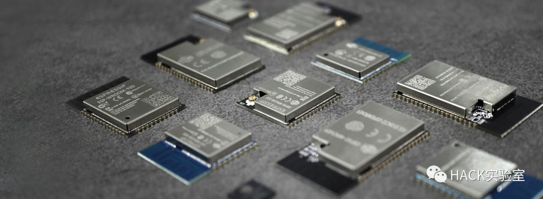
Another consideration is the main control unit. Previously, for the OLED clock, I used the STM32F103RE, which is a standard ARM core microcontroller. To be honest, using it for a clock is a bit of an overkill, not in terms of price but in performance. Additionally, it does not have WiFi functionality. So I thought about it, and the ESP8266 and ESP32 from Espressif are the most suitable choices, mainly due to their low price and comprehensive features, plus they support Arduino IDE. The ESP32 has better performance but is more expensive; the ESP8266 is sufficient for a clock. Therefore, I ultimately chose the ESP8266.
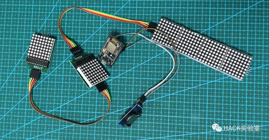
After verifying the scheme, I felt that the 30*30mm dot matrix screen was a bit large and not refined enough, so I looked on Taobao to see if there was a smaller size available, and indeed there was, 20*20mm, which was just right, so I placed an order without hesitation. Next comes the board design, which I enjoy doing. Over the past few years, I haven’t gone more than a week without designing a board; it has become a lifestyle for me.
Of course, I still use KiCad for board design. In my previous article, I briefly introduced this EDA software and sincerely recommend everyone to give it a try; it is absolutely useful. When designing the board, I also have a philosophy of minimizing components while ensuring performance, removing unnecessary components. This makes the project as simple as possible, allowing beginners to easily replicate it.
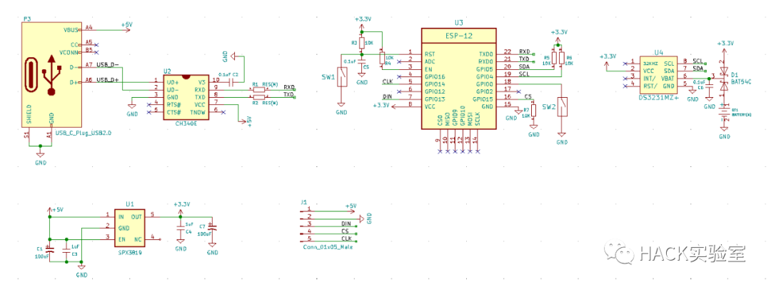

Here is the schematic and PCB for a quick look; you can download the project files to see the details.
First is the choice of USB interface. There are two options: either Type-C or Micro-USB. Friends who have read my previous articles should know that I wrote one about Type-C, which has many advantages, so I undoubtedly chose the Type-C interface. It is mainly used to power the entire system and connect to a computer for program downloading and debugging. (The model used in this project is the TYPE-C-31-M-14 from Korea’s Hanrong.)
Also about the power supply choice. My main job involves industrial IoT, and I often use various wireless modules, including WiFi, sub1G, GSM, 4G, etc. Wireless modules have specific power requirements, especially for WiFi, GSM, and 4G, which require higher power supply capacity. They can draw a large current when connecting to the network, and if the power supply cannot meet this demand, the connection will fail. Therefore, I did not choose a regular low-current LDO but instead opted for an LDO chip that can provide a supply current of up to 500mA—SPX3819, accompanied by capacitors. Another reason for using this LDO is its low cost, less than one yuan, making it very economical.
Choice of clock chip. Last time, I chose the RX8025-T for the OLED clock, which is a high-precision temperature-compensated clock chip developed by Epson for power systems, known for its high precision. The last OLED clock I ran continuously for over a month, and it was accurate to the second compared to standard time. However, this time I did not choose the RX8025-T but instead selected another excellent clock chip, the DS3231MZ+. You may be familiar with the DS3231 but not the MZ+ suffix; both have the same functions and usage, including temperature compensation, but the MZ+ version is in a smaller SOP-8 package, saving space. I learned about it from some open-source projects abroad and recommend it for use in space-constrained projects.
Choice of main control. As mentioned above, I chose the ESP8266 for its comprehensive features and ease of use. Pairing the ESP8266 with Arduino IDE is incredibly convenient, and with a wealth of open-source projects available on GitHub, you can find almost any driver related to maker DIY projects. I recommend beginners to try it out; NodeMcu is a good choice. (The module used in this project is ESP-12E, priced around ten yuan.)
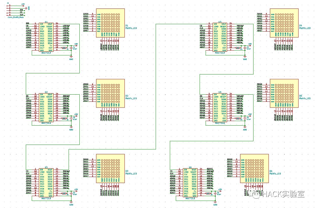
Display module design. I also mentioned the reasons for choosing the display module. When purchasing components, there are two points to note: 1. The dot matrix is a 20*20mm common cathode screen. 2. The driver chip is MAX7219 in a surface mount package. Here is the schematic PCB for the display section for a quick look; you can download the drawings for detailed study.

In the resource package, you can find the software folder, which contains the software program for this clock, written using Arduino IDE. After connecting the clock hardware to the computer via USB, you need to install the driver. We use the CH340 from Nanjing Qinheng Microelectronics; you can download and install it directly from their official website.
If you are using Arduino IDE for the first time, you need to download and install it; it’s very simple, so I won’t go into detail here. Then, open the project file with Arduino IDE. Since Arduino does not initially support the ESP8266 development board, and our clock is designed based on NodeMcu, you can directly install the NodeMcu development board. The specific process is to enter the following URL in File – Preferences – Settings – Additional Board Manager URLs: http://arduino.esp8266.com/stable/package_esp8266com_index.json. Then go to Tools – Board and select NodeMcu 1.0 (ESP-12E Module).
Once everything is ready, you can compile it and install the necessary libraries as prompted. (You need to change the WiFi information to your home WiFi account and password in the program.) In Tools – Port, select the COM port where our board is located, then long press the Download button on our board while briefly pressing the Reset button. At this point, click upload on the IDE and wait for the download to complete before releasing the Download button.

This concludes the introduction to the dot matrix LED clock. I hope it helps everyone, and if you are interested, you can try making it yourself. I also hope that capable friends can expand on this project and create more interesting things to share with everyone. If you have any questions, feel free to leave a message or send me a private message.
Here, I would like to mention my upcoming open-source project plan: I am planning to make an open-source desktop audio amplifier, using TI’s TPA3116, paired with high-end operational amplifiers. The main reason for this project idea is that the desktop amplifier I bought from another company, priced around 300 yuan, has been used for over two months and feels quite subpar, failing to meet my needs, which led to this project idea. Please leave your thoughts or suggestions on this project in the comments.
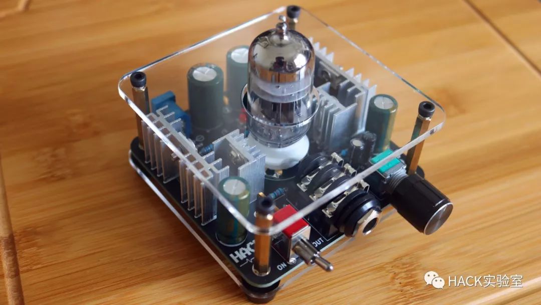
Finally, I want to thank friends who purchased the ear amplifier to support 「HACK Laboratory」 on Taobao; this part of the income will be used for purchasing instruments and funding upcoming open-source projects, bringing more valuable content to everyone.
Thank you all; your support is my motivation for creation.
Why I Choose KiCad as My Main EDA Software
An Analysis of the RISC-V Instruction Set Architecture System Sharing the Power-On Startup Process of STM32 Deep Analysis of STM32 Microcontroller’s RAM and FLASH An Article Explaining TVS Transient Voltage Suppressor Diodes Have You Heard of the 4-20mA Current Loop Transmission Method? Some Issues You Need to Know About the 485 Bus
