【Introduction】Anyone working as an electrician knows that when equipment suddenly shuts down, the most frustrating task is troubleshooting external faults: measuring a bunch of sensors, solenoids, and wiring repeatedly, checking from the power supply to the load, only to find after half an hour that it was a broken wire on the proximity switch. This not only delays production but can also exacerbate faults due to blind troubleshooting. In fact, by designing a simple external fault diagnosis circuit using the Mitsubishi FX3U PLC, fault localization can be simplified, even achieving “self-reporting” of faults. The core logic of this circuit is straightforward: assign a “fault monitoring point” to each external actuator (such as solenoids Y0, Y1) and detection element (such as photoelectric sensors X0, X1). The PLC program checks whether the “command output” matches the “actual feedback”; if there is a discrepancy, it immediately triggers the corresponding fault indicator light, accurately pinpointing the issue.
Learning Objectives
1. Familiarize with alarm setting and resetting instructions.
2. Understand programming techniques.
3. Be able to write ladder diagram programs using alarm setting and resetting instructions for external fault diagnosis circuits.
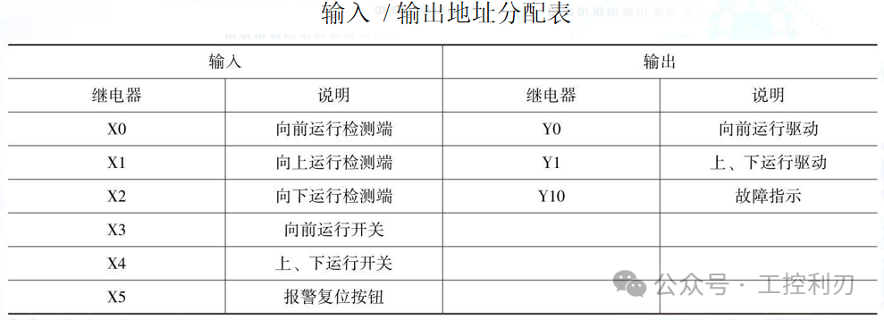
The ladder diagram for the external fault diagnosis circuit designed is shown in the figure. The status flags S900 ~ S999 are signal alarms, used in the alarm setting instruction ANS and alarm resetting instruction ANR, serving as outputs for external fault diagnosis. The special auxiliary relay M8049 indicates the validity of the alarm; if it is activated, it means monitoring is effective. The PLC stores the minimum address number of the action status from S900~S999 in the special data register D8049. The special auxiliary relay M8048 indicates the alarm activation; if M8049 is activated, any action in the status flags S900 ~ S999 will cause M8048 to activate.
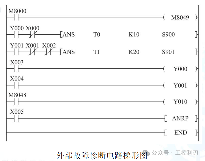
If the normally open contact of M8000 is continuously connected, the coil of M8049 is energized, and the monitoring function of the special data register D8049 is valid. When the forward run switch is pressed, Y0 is ON, driving the machine forward. If within 1 second after the machine moves forward, the forward run detection terminal X0 does not work, it indicates that the machine has not moved forward, and S900 activates, indicating a fault. If the input circuit of instruction ANS is disconnected, the timer T0 resets, while S900 remains ON. When the up and down run switches are pressed, Y1 is ON, driving the machine to run up and down. If within 2 seconds after the machine runs up and down, both up and down run detection terminals X1 and X2 do not work, it indicates that the machine has not moved up or down, and S901 activates, indicating a fault.
If any of S900 ~ S999 is activated, M8048 activates, and the fault indicator Y10 operates. The alarm reset button can be used to set the action status caused by the external fault diagnosis program to OFF. Each time X5 is activated, the action status of the new address number will be reset in order.
1
Alarm Setting Instruction (ANS)
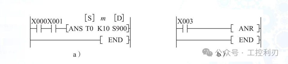
The source operand [S] for ANS is T0 ~ T199, the target operand [D] is S900 ~ S999, and the timer setting value m = 1 ~ 32,767 (in units of 100 ms).
2
Alarm Resetting Instruction (ANR)
ANR has no operands, as shown in the figure above. If X003 is activated, the signal alarms S900 ~ S999 that are currently active will be reset. If multiple signal alarms are active, the status of the new address number will be reset. If X003 is activated again, the next address number’s signal alarm will be reset.
If the instruction is continuous execution type, the fault alarms will be reset in order during each operation cycle; if the instruction is pulse execution type, each time the reset button X003 is pressed, one fault alarm status will be reset in the order of the component number. When a fault occurs, the corresponding alarm status will be ON; if multiple faults occur simultaneously, D8049 will contain the component number of the lowest address alarm that has been set. After resetting it, D8049 will contain the component number of the next lowest address alarm that has been set.
3
Programming Techniques
Data Calculation and Conversion
In PLC control, there are many occasions where numerical calculations and conversions are required, such as processing analog and digital signals, arithmetic operations, function operations, PID processing, etc. When designing such programs, first draft the calculation formula based on control requirements, then gradually complete the calculations using relevant instructions, paying attention to the storage of intermediate calculation results during programming.
Using a certain data as a control condition
Many control scenarios use numerical values as control conditions, such as when temperature or pressure reaches a certain value, the next operation is triggered. These programs rely on transfer comparisons, usually using the comparison result components of comparison instructions as switches for the next process.
Using data for logical control
The purpose of designing a ladder diagram is to achieve outputs that meet control requirements. In basic instruction logic control tasks, outputs are treated as independent, and each output’s ladder diagram branch is designed separately. In application instruction programs, the PLC’s output ports are treated as word components, and the state of the output port at a certain moment is treated as data.
Using application instructions to form certain patterns
In industrial control, many control objects need to operate in a certain cyclic manner, such as stepper motors requiring regular pulses, or colored lights forming a flowing light pattern. This requires internal devices to form the required patterns, and such programs rely on shifting, encoding, and decoding. When programming, first find suitable instructions based on single-cycle control requirements, then consider how to implement the cycle.
Data Management
When there are many intermediate data, backup data, or historical data in control, scientific management of data is required.
Initialization and Resetting of Data Register Units
Programming cannot do without the initialization of programs and the resetting of data register units. These functions are usually implemented after the main functionality is achieved by adding relevant program segments in the program. Among them, the implementation of cyclic functions often relies on increment instructions, decrement instructions, reset instructions, and index registers.
 Click below “Previous Recommendations” to learn more information
Previous Recommendations
Hiring 5 Electrical Assemblers!
Hiring Electrical Engineers: 10k-15k! Interested parties please contact directly by phone
PLC Programming Total Report “Invalid Address”? Understand these 3 types of storage ranges, and never fall into memory pitfalls again!
Hiring Electrical Engineers! 12k-25k
Hiring 10 Assembly Electricians, 6k-10k!
Stuck on PLC Basics? 90% of people stumble on these 6 data types! This article will clarify everything for you!
Hiring! Hiring! Hiring! 8.5k-12.5k
Complete Guide to Wiring 3 Types of Intermediate Relays: 8-pin/11-pin/14-pin Error Prevention Guide, Essential for Electricians!
“Nanny-level” tip to help you master the wiring of proximity switches controlling solenoids!
Hiring: Die Casting Machine Repair 9K-11k