Author | Sensor Technology
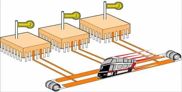
The bus, known in English as “BUS”, is a very vivid analogy. Just like a public bus that follows a fixed route, anyone can take the bus to any stop along that route. If we compare people to electronic signals, that is the true meaning behind calling it a “BUS” instead of a “CAR”. Professionally speaking, a bus is a structural form that describes the transmission lines of electronic signals, a collection of signal lines, and a public channel for transmitting information between subsystems. The bus allows for the transmission, exchange, sharing, and logical control of information among the components within the entire system. For example, in a computer system, it serves as the public channel for information transfer between the CPU, memory, input, and output devices. The various components of the host are connected through the host, and external devices connect to the bus through corresponding interface circuits.
The development of modern network information, especially in terms of cost and space, has made bus transmission a hot topic, replacing point-to-point transmission. Its emergence provides the greatest convenience and the most effective technical solutions for information transmission.
Basic Components of the System Bus
Data Bus: Transmits data information
Address Bus: Transmits address information
Control Bus: Transmits control information (completes bus operation functions)
Power Line: Provides power signals for the system
Functions of the Bus
1. Data Transmission Function
The data transmission function is the basic function of the bus, represented by the bus transmission rate, which is the number of bytes transmitted per second, measured in Mbps (megabytes per second).
2. Multi-Device Support Function
Multiple devices use a single bus. The issue of bus occupancy rights arises, where the bus arbiter determines which master device requests to occupy the bus.
3. Interrupts
Interrupts are the mechanism by which a computer responds to urgent tasks. When an external device and the master device agree on service, interrupts serve as the contact signal for implementing the service agreement.
4. Error Handling
Error handling includes detecting and processing errors such as parity errors, system errors, and battery failures, as well as providing appropriate protective measures.
Data Transmission Process of the Bus
1. Request to Occupy the Bus
The bus master device (such as CPU, DMA controller, etc.) that needs to use the bus requests to occupy it from the bus arbitration agency. If the response conditions are met, the bus arbitration agency issues a response signal and grants the control of the bus for the next transmission cycle to the requester.
2. Addressing
The bus master device that obtains control of the bus issues the address of the memory and I/O port to be accessed through the address bus, selects the accessed module through address decoding, and begins data conversion.
3. Data Transmission
The bus master device, also known as the master module, and the accessed device, known as the slave module, perform operations controlled by the master module to transmit data between the two slave modules through the data bus.
4. End
Both master and slave module information is removed from the bus, releasing the bus for use by other master modules.
Types of Microcomputer Buses
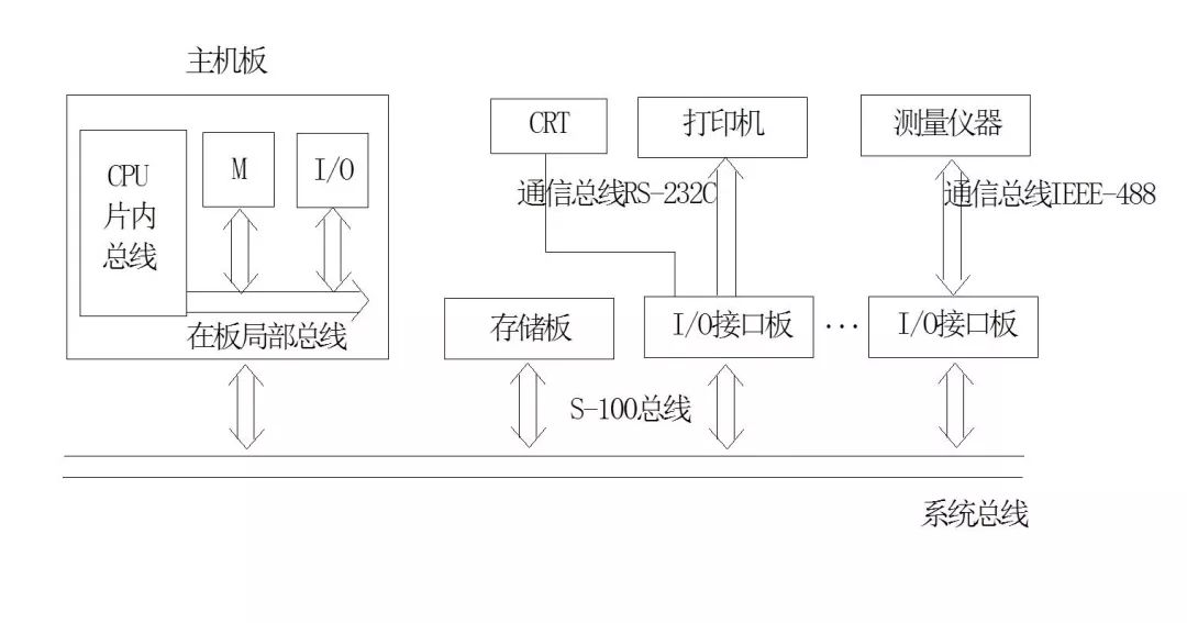
On-Chip Bus
This is the bus located between the internal circuits of large-scale and ultra-large-scale integrated chips, serving as the information pathway between these unit circuits, such as the bus between the CPU’s ALU, register group, and controller.
Local Bus (also known as Internal Bus)
Typically refers to the information pathway between components on a microcomputer motherboard. Since it is a bus within a circuit board, it is also referred to as a local bus on the board. Typical local buses include the IBM-PC bus, ISA bus, EISA bus, VL, and PCI bus.
System Bus (also known as External Bus)
This refers to the bus on the baseboard of a microcomputer, used to form the channels between various plug-in boards of the microcomputer system and between CPU modules in multi-processor systems. Typical system buses include STD-BUS, MULTI-BUS, and VME.
Communication Bus
This is the information pathway between microcomputer systems and between microcomputer systems and other instruments or devices. This type of bus is often not exclusive to computers but utilizes existing bus standards from other fields of the electronics industry. Popular communication buses include EIA-RS-232C, RS-422A, RS-485, IEEE-488, and VXI bus standards.
Relationship Between Various Buses
Advantages of Using Bus Technology
1. Simplified Software and Hardware Design: Due to the strict definition of the bus, any manufacturer or individual must produce plug-in boards according to its standards, providing users with great convenience in hardware design and simplifying the design process.
2. Simplified System Structure: By using a standard bus, various functional modules (boards) can be easily connected to form the hardware system of the microcomputer.
3. Easy System Expansion: For microcomputer systems constructed using standard buses, simply designing or directly purchasing plug-in boards according to bus standards and user expansion requirements achieves the goal of expansion.
4. Easy System Updates: With the continuous development of electronic technology and the emergence of new devices, microcomputer systems must also be continuously updated. Using new devices to replace the original ones on standard bus plug-in boards can conveniently improve system performance without significant modifications.
Classification of Bus Technology
There are many ways to classify buses, such as external and internal buses, system buses and non-system buses, etc.
1. By Function
The most common classification is based on functionality, dividing data buses into address bus, data bus, and control bus. In some systems, data and address buses can be shared under address latching control, meaning they can be multiplexed.
The address bus is specifically used to transmit addresses. In the design process, the most common should be selecting the storage address of external memory from the CPU address bus. The bit width of the address bus often determines the size of the memory storage space. For example, a 16-bit address bus can address a maximum storage space of 2^16 (64KB).
The data bus is used to transmit data information, which can be classified into unidirectional and bidirectional data buses. Bidirectional data buses usually adopt a tri-state form. The bit width of the data bus is typically consistent with the word length of the microprocessor. For instance, the Intel 8086 microprocessor has a word length of 16 bits, and its data bus width is also 16 bits. In practice, the data transmitted on the data bus is not necessarily complete data.
The control bus is used to transmit control signals and timing signals. For example, when the microprocessor operates on external memory, it must first send read/write signals, chip selection signals, and interrupt response signals through the control bus. The control bus is generally bidirectional, and its transmission direction is determined by specific control signals, with its bit width depending on the actual control needs of the system.
2. By Transmission Method
Based on the method of data transmission, buses can be divided into serial and parallel buses (based on various bus technology design circuit collections). In principle, parallel transmission is superior to serial transmission, but the cost will increase. Simply put, the path of parallel transmission is like a multi-lane highway, while serial transmission allows only one car to pass through a single-lane road. Currently, common serial buses include SPI, I2C, USB, IEEE1394, RS232, CAN, etc.; while parallel buses are relatively fewer, with common types like IEEE1284, ISA, PCI, etc.
3. By Clock Signal Method
Based on whether the clock signal is independent, buses can be classified into synchronous and asynchronous buses. The clock signal of a synchronous bus is independent of the data, meaning a separate line is used as the clock signal line; while the clock signal of an asynchronous bus is extracted from the data, usually using the edges of the data signal as the clock synchronization signal.
Basic Principles of Bus Transmission
Based on the previous definition of the bus, it is clear that the fundamental role of the bus is to transmit signals. To ensure that information from various subsystems is effectively and timely transmitted without mutual interference and to avoid excessive physical space congestion, the best method is to use multiplexing technology. In other words, the basic principle of bus transmission is multiplexing technology. Multiplexing refers to a mechanism where multiple users share a common channel. Currently, the most common types include Time Division Multiplexing (TDM), Frequency Division Multiplexing (FDM), and Code Division Multiplexing (CDM).
Time Division Multiplexing (TDM)
Time division multiplexing divides the channel into multiple time slots; signals from different sources request a response within different time slots, and the transmission times of each signal do not overlap on the time axis.
Frequency Division Multiplexing (FDM)
Frequency division multiplexing divides the available frequency band of the channel into several non-overlapping frequency bands, with each signal occupying one of these bands after frequency modulation to enable transmission of multiple signals with different frequencies over the same channel. When the receiving end receives the signal, appropriate bandpass filters and frequency demodulators are used to restore the original signal.
Code Division Multiplexing (CDM)
Code division multiplexing assigns a specific identification code or address code to each transmitted signal. The receiving end distinguishes the transmitted information on the common channel based on different identification codes or address codes, and only when the identification code or address code matches completely will the transmission information be received.
Main Technical Indicators of the Bus
The main technical indicators for evaluating a bus are its bandwidth (i.e., transmission rate), data bit width (bit width), operating frequency, and the reliability and stability of data transmission.
Bandwidth (Transmission Rate), Bit Width, and Operating Frequency
The bandwidth of the bus refers to the amount of data transmitted on the bus per unit time, that is, the maximum data transmission rate per second. The bit width of the bus refers to the number of binary data bits that can be transmitted simultaneously or the width of the data bus, such as 32-bit, 64-bit, etc.; the wider the bus bit width, the greater the data transmission rate, and the wider the bus bandwidth. The operating clock frequency of the bus is measured in MHz, and it is related to the transmission medium, signal amplitude, and transmission distance. Under the same hardware conditions, using differential signal transmission often achieves a much higher frequency than single-ended signals. This is because the amplitude of the differential signal is only half that of the single-ended signal.
The relationship between the bus’s bandwidth, bit width, and operating frequency is closely related:

Reliability of Data Transmission
Reliability is the most critical parameter for evaluating a bus. Without reliability, the transmitted data is erroneous information, which defeats the practical purpose of the bus. To improve the reliability of the bus, common measures include:
1. Using a data frame to listen to the bus before transmission, allowing data frames to be sent only when the bus is idle, thereby avoiding data conflicts between different nodes.
2. Using twisted pair differential signals for data transmission to reduce the voltage swing of a single line and decrease the high-order harmonics generated by signal edges.
3. Appropriately allowing the edges of the data to have a certain slope.
4. Increasing matching resistors and capacitors to reduce signal transmission and balance the distributed capacitance on the bus.
5. Using appropriate network topologies and shielding techniques to minimize interference from other signals.
Several Typical Bus Technologies and Their Characteristics
STD System Bus
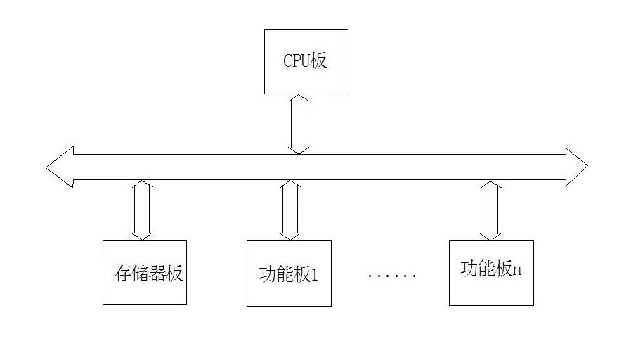
1. Modular small board structure, open flexible configuration
The STD bus divides the microcomputer system into several modules and produces standard functional templates (plug-in cards). Users can select functional templates to assemble their microcomputers based on their needs, and plug-in cards can be connected to peripherals using other methods, making it easy to construct microcomputer systems that meet different requirements.
2. High reliability, high anti-interference capability, and high signal quality
The excellent physical characteristics of the STD bus enable it to withstand harsh environments. Its modular small size structure gives it resistance to shock and vibration, while also reducing self-generated heat issues. Since the STD bus uses printed circuit board edges for connectors, it prevents plug-in cards from being incorrectly inserted, with pins bending or breaking. Additionally, the structure of the STD bus allows for orderly signal flow from the bus interface to the user interface, improving signal quality.
3. Compatible structure, supporting products, and comprehensive functions
The compatible structure of the STD bus allows 8-bit STD products to work alongside new standard 16-bit or 32-bit STD products. The STD bus also supports multi-processor systems. With technological advancements and the promotion and application of STD products, the functionality of standard plug-in boards continues to enhance, and supporting products are becoming increasingly rich, greatly facilitating users.
RS-232C Communication Bus
RS-232C is a serial communication bus standard and also the interface standard between data terminal equipment (DTE) and data communication equipment (DCE). It was derived from the CCITT remote communication standard by the Electronic Industries Alliance (EIA) in 1969. The initial purpose of establishing this standard was to ensure that devices produced by different manufacturers could achieve plug compatibility, meaning that as long as a device has an RS-232C standard interface, it can be connected without any conversion circuits. However, this standard only guarantees hardware compatibility, not software compatibility.
The RS-232C standard includes mechanical and electrical specifications, with the mechanical specification stating that the RS-232C standard interface’s external connection (pins and sockets) is a 25-pin “D” type connector.
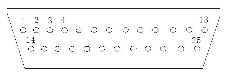
Main Features of RS-232C
1. Fewer signal lines: The RS-232C bus has a total of 25 lines, including both main and secondary channels, allowing for duplex communication. In practical applications, most only use the main signal channel (the first channel) and typically only a few signals (usually 3 to 9 lines).
2. Long transmission distance (relative to parallel): Since RS-232C uses serial transmission and converts TTL levels to RS-232C levels, the distance can reach 30m during baseband transmission. If using optical isolation for a 20A current loop, the distance can reach 1000m. Of course, if a modem is added to the serial interface, the distance can be even greater using wired, wireless, or fiber optics for transmission.
3. Multiple selectable transmission rates: The standard transmission rates specified by RS-232C include: 50, 75, 110, 150, 300, 600, 1200, 2400, 4800, 9600, 19200 baud. It can be flexibly used with devices of different rates.
4. Strong anti-interference capability: RS-232C uses negative logic, where idle states are represented by any voltage between +3V and +25V for logic “0”, and any voltage between -3V and -25V for logic “1”. It also uses non-return-to-zero signaling, greatly enhancing its anti-interference capability.
RS-422A Bus
RS-422A employs a balanced output transmitter and a differential input receiver. The transmitter has two output lines, where one line transitions to high while the other transitions to low, thus flipping the voltage polarity between the lines. Sending signals on RS-422A requires two lines, and receiving signals also requires two lines. For duplex communication, at least four lines are needed. Since RS-422A lines are fully balanced, a common ground line is generally not used, minimizing interference due to different ground potentials between the communicating parties. Common-mode interference caused by differing ground potentials is filtered out by the differential receiver, which can cause errors on RS-232C lines.
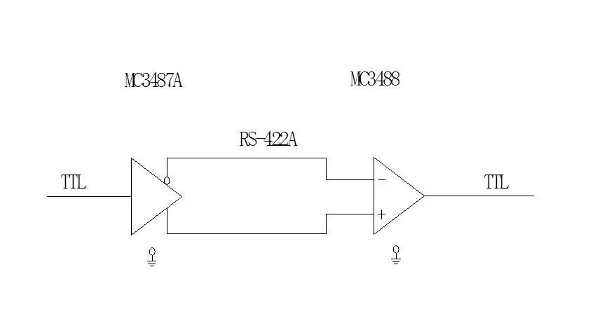
RS-485 Bus
The RS-485 bus uses interface circuits for full-duplex communication, requiring two pairs of wires or four wires, increasing line costs. RS-485 is suitable for communication between two parties sharing a pair of wires, and can also be used for bus networking between multiple points sharing a pair of lines, though communication is half-duplex.
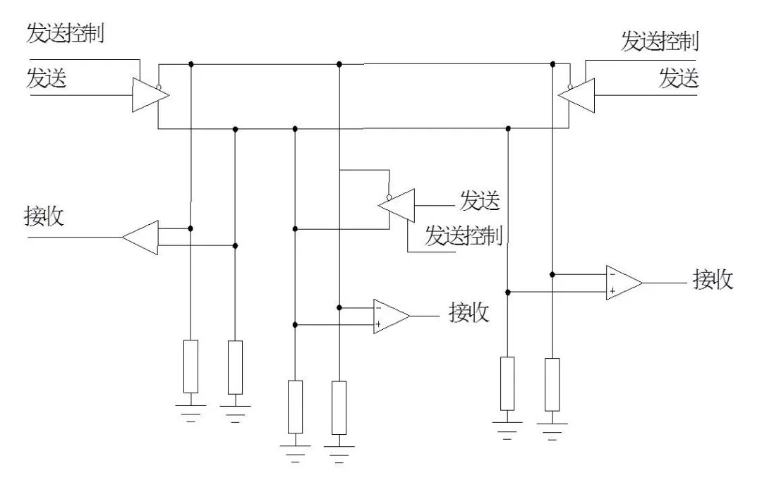
Since only one transmitter is allowed to send data at any time, other transmitters must remain off (high impedance). This is controlled by the send enable pin on the transmitter chip. For example, when this pin is high, the transmitter can send data, while when it is low, both output terminals of the transmitter present high impedance, as if disconnected from the line.
IEEE 488 Bus
IEEE 488 is a parallel external bus that was established by HP in the 1970s. In 1975, it was recommended as the IEEE-488 standard bus, and in 1977, it was recognized and recommended by the International Electrotechnical Commission (IEC), named IEC-IB. Therefore, this bus is known by multiple names, including IEEE-488, IEC-IB (IEC Interface Bus), HP-IB (HP Interface Bus), or GP-IB (General Purpose Interface Bus). The introduction of the IEEE-488 bus allows for the construction of a computer-controlled testing system without the need for complex control circuits. The IEEE-488 system primarily consists of rack-mounted intelligent instruments, forming an open modular testing system, making the IEEE-488 bus one of the most widely used communication buses in industry today.
Agreements for using the IEEE-488 bus: 1. Data transmission rate ≤ 1MB/S. 2. The number of devices connected to the bus (including the microcomputer acting as the controller) ≤ 15. 3. The maximum distance between devices ≤ 20M. 4. The total length of the entire system’s cable ≤ 220M; if the cable length exceeds 220M, timing relationships may change due to delays, causing unreliable operation. In such cases, a modem should be added. 5. All digital exchanges must be digitalized. 6. The bus specifies the use of a 24-wire combination connector, employing negative logic, where logic “1” is represented by a level less than +0.8V, and logic “0” is represented by a level greater than 2V.
Operating modes of devices on the system: 1. “Listener” mode: This is a receiver that receives data on the data bus; a system can have more than two listeners working simultaneously. 2. “Talker” mode: This is a transmitter; a system can have more than two talkers, but only one talker can work at any given time. 3. “Controller” mode: This is a device that issues commands to other devices, such as addressing other devices or allowing a talker to use the bus. Only one controller can operate at any given time.
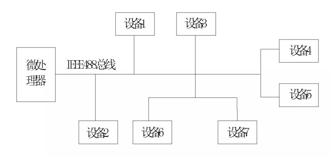
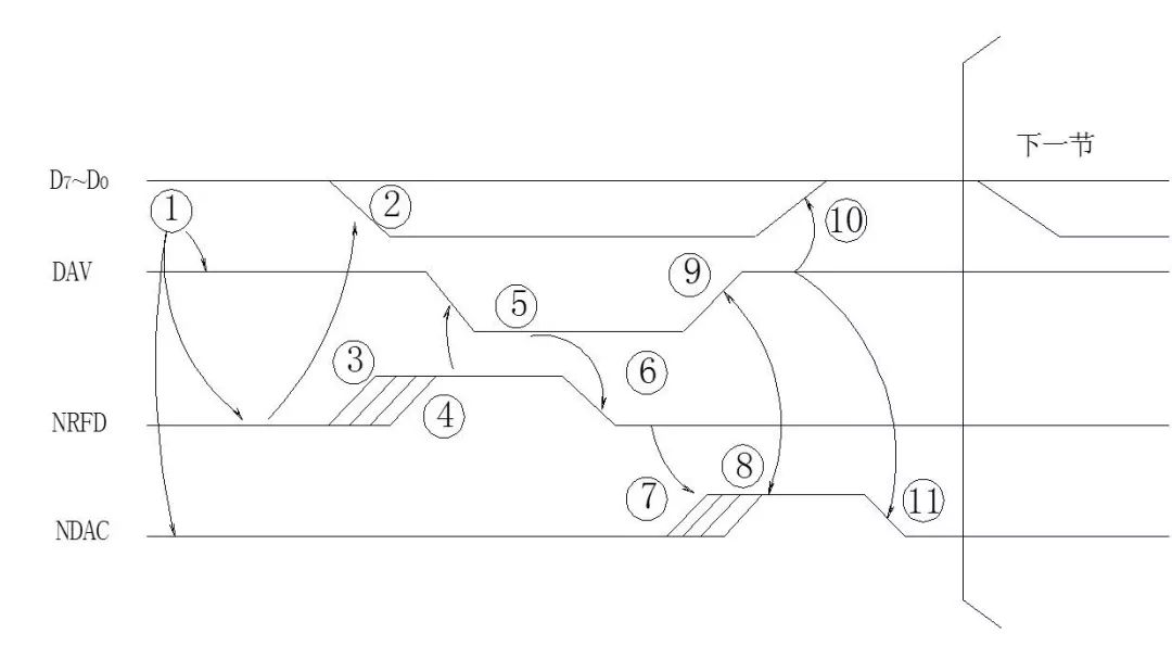
Data transmission timing of the IEEE-488 bus: Data transmission on the IEEE-488 bus is asynchronous, meaning that each byte of data transmission requires handshake communication using three signal lines: DAV, NRFD, and NDAC.