The CAN bus terminal resistor, as the name suggests, is the resistor added at the end of the bus. Although small, this resistor plays a very important role in CAN bus communication.
The Role of Terminal Resistors
There are two main roles of the CAN bus terminal resistor:
1. Improve anti-interference capability, ensuring the bus quickly enters a recessive state;
2. Improve signal quality.
Improving Anti-Interference Capability
The CAN bus has two states: “dominant” and “recessive”. The “dominant” state represents “0” and the “recessive” state represents “1”, determined by the CAN transceiver. Figure 1 shows a typical internal structure of a CAN transceiver, with CANH and CANL connected to the bus.
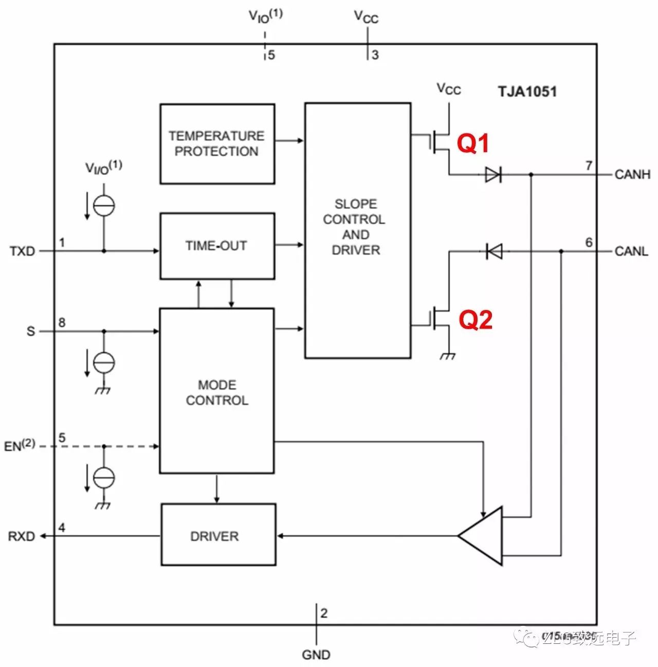
Figure 1
When the bus is in the dominant state, the internal Q1 and Q2 of the transceiver are conducting, creating a voltage difference between CANH and CANL; in the recessive state, Q1 and Q2 are cut off, and CANH and CANL are in a passive state, with a voltage difference of 0.
If there is no load on the bus, the differential resistance value in the recessive state is very high, and external interference requires only a small amount of energy to make the bus enter the dominant state (the minimum voltage threshold for a typical transceiver in the dominant state is only 500mV). To enhance the anti-interference capability of the bus in the recessive state, a differential load resistor can be added, and its resistance value should be as small as possible to eliminate the impact of most noise energy. However, to avoid requiring too much current for the bus to enter the dominant state, the resistance value cannot be too small.
Ensuring Quick Entry to Recessive State
During the dominant state, the parasitic capacitance of the bus will be charged, and when returning to the recessive state, these capacitors need to discharge. If no resistive load is placed between CANH and CANL, the capacitors can only discharge through the internal differential resistance of the transceiver. We added a 220PF capacitor between CANH and CANL in the transceiver for a simulation experiment at a bit rate of 500kbit/s, with waveforms shown in Figures 2 and 3.
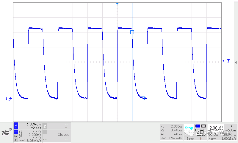
Figure 2
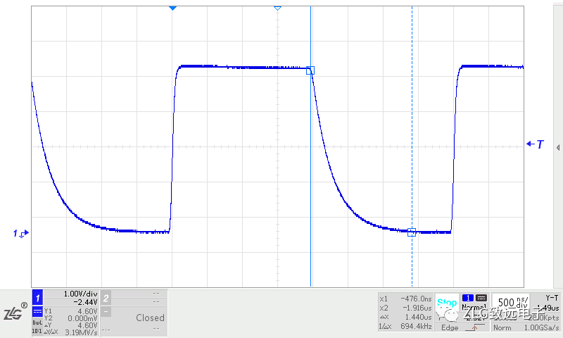
Figure 3
From Figure 3, it can be seen that the time taken to recover from dominant to recessive state is as long as 1.44μS, making communication barely possible at higher sampling points. If the communication rate is higher or the parasitic capacitance is larger, it is difficult to ensure normal communication.
To allow the bus parasitic capacitance to discharge quickly and ensure the bus quickly enters the recessive state, a load resistor needs to be placed between CANH and CANL. After adding a 60Ω resistor, the waveforms are shown in Figures 4 and 5. From the figures, it can be seen that the time taken to recover from dominant to recessive state is reduced to 128nS, comparable to the dominant establishment time.
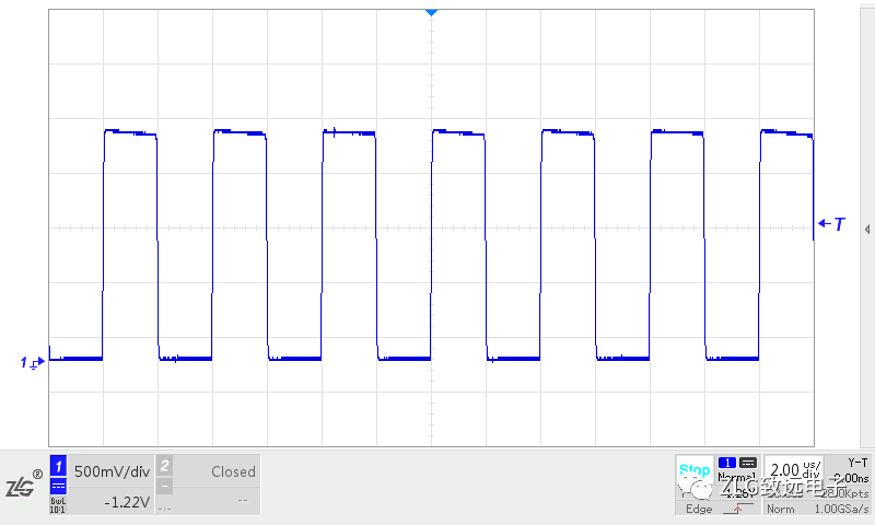
Figure 4
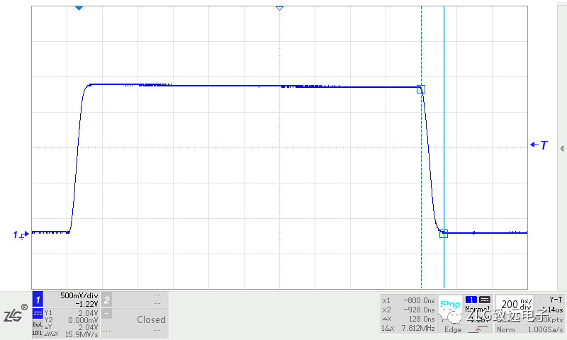
Figure 5
Improving Signal Quality
At higher transition rates, when the signal edge energy encounters impedance mismatch, signal reflection occurs; changes in the geometric structure of the transmission cable cross-section can also cause changes in the cable’s characteristic impedance, leading to reflections.
At the end of the bus cable, a sudden change in impedance causes signal edge energy to reflect, resulting in ringing on the bus signal. If the amplitude of the ringing is too large, it will affect communication quality. Adding a terminal resistor that matches the cable’s characteristic impedance at the end of the cable can absorb this part of the energy and prevent ringing from occurring.
We conducted a simulation experiment at a bit rate of 1Mbit/s, connecting a transceiver’s CANH and CANL to a twisted pair cable of about 10m, with a 120Ω resistor at the transceiver end to ensure recessive transition time, and no load at the end. The end signal waveform is shown in Figure 6, where ringing occurs on the rising edge of the signal.
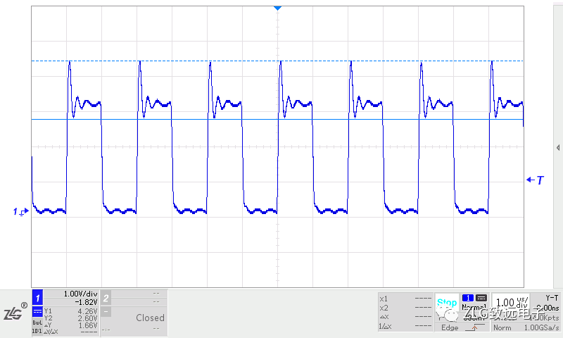
Figure 6
If a 120Ω resistor is added at the end of the twisted pair cable, the end signal waveform improves significantly, and the ringing disappears, as shown in Figure 7.
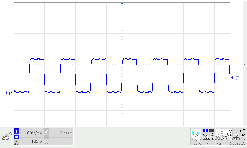
Figure 7
In a linear topology, both ends of the cable serve as both the transmitter and receiver, so a terminal resistor should be added to each end of the cable.
Why Choose 120Ω
The characteristic impedance of any cable can be determined experimentally. One end of the cable is connected to a square wave generator, while the other end is connected to a variable resistor, and the waveform on the resistor is observed using an oscilloscope. Adjust the resistance value until the signal on the resistor is a good, ringing-free square wave; the resistance value at this point can be considered consistent with the cable’s characteristic impedance.
Most automotive cables are single wires. If you take two typical automotive cables and twist them into a twisted pair, you can obtain a characteristic impedance of about 120Ω using the method described above, which is also the terminal resistor value recommended by the CAN standard.
For more technical topics, reply with the keyword 【Power Supply】.
Official WeChat Account Introduction
The official WeChat account of Zhiyuan Electronics, a research and testing sharing platform with 500 engineers, provides you with leading product technologies and solutions in the electronics industry..