Follow our official account, click the “···” in the upper right corner of the homepage to set a star mark, and stay updated on the latest news in intelligent automotive electronics and software.
 Source: Automotive Electronics and Software Author: JawSoWThe CAN protocol message transmission process includes:Data Frame, Remote Frame, Error Frame, Overload Frame, and Frame Interval.1. Data Frame: A frame used to send data from the sending node to the receiving node.2. Remote Frame: A frame used by the receiving node to request data from a sending node with the same ID.3. Error Frame: A frame used to notify other nodes of an error when detected.4. Overload Frame: A frame used by the receiving node to indicate it is not ready.5. Frame Interval: Used to separate data frames and remote frames from the previous frame.Standard Frame and Extended Frame:
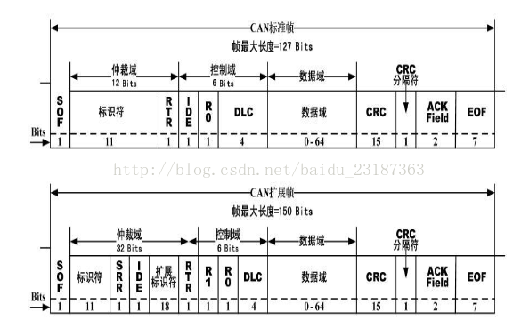 Both data frames and remote frames can use either standard frame format or extended frame format.RTR: Remote Transmission Request bit, data frame is explicit, remote frame is implicit.SRR: Replaces the remote request bit (in extended format at the RTR position, hence the name), this bit is implicit. This bit is used to align the standard frame and extended frame IDE, allowing determination that standard frames take priority over extended frames.IDE: Identifier Extension bit, standard frame is explicit, extended frame is implicit.R0, R1: Reserved bits.DLC: Data Length Code.CRC: Checksum bit.CRC Separator: Implicit bitACK: Acknowledgment bit and acknowledgment delimiter. In the acknowledgment domain, the transmitter sends two implicit bits. After the receiver receives the message, it fills the acknowledgment bit with an explicit bit as a response, and the acknowledgment delimiter remains implicit.Frame End: Consists of 7 implicit bits.Data Frame:
 SOF Frame Start: The segment marking the start of the data frame.Arbitration Field: The segment indicating the priority of the frame.Control Field: The number of bytes of data and reserved bits.Data Field: The content of the data.CRC Field: Check data.Acknowledgment Field: The segment confirming normal reception.Frame End: The segment marking the end of the data frame.Remote Frame:
 By sending a remote frame, the node acting as the data receiver can initiate a request for data transmission from its data source, i.e., request the data sender to send a data frame with the same ID. The remote frame does not have a data segment.Error Frame:
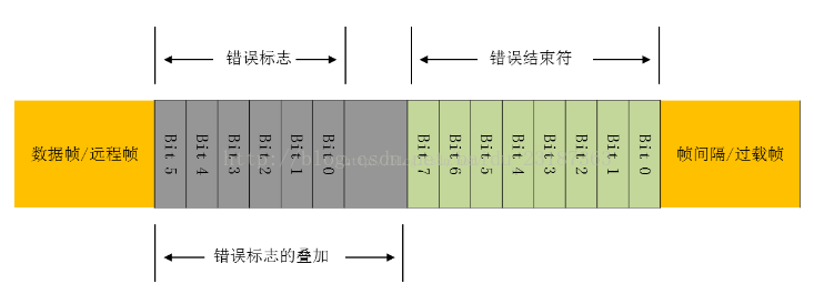 Error Types: Acknowledgment Error, Bit Stuffing Error, CRC Error, Format Error The error frame consists of an overlay of error flags and an end delimiter. The error flags consist of active (positive) error flags and passive (negative) error flags. The active (positive) error flag consists of 6 explicit bits, while the passive (negative) error flag consists of 6 implicit bits. Active error node: If an error condition is detected, it will send an active error flag. This will cause other nodes to detect a bit stuffing error and start sending an error flag. Therefore, the error flag overlays between bits 6 and 12. After sending the error flag, the node sends an implicit bit and monitors the bus until an implicit bit appears on the bus, and then sends 7 implicit bits. Thus, an error frame is completed. Passive error node: If an error condition is detected, it will attempt to send a passive error flag for indication. This passive error node will wait for 6 consecutive bits of the same polarity, waiting for the passive error flag to start. When it detects 6 consecutive bits of the same polarity, the passive error flag sending is completed. Overload Frame:
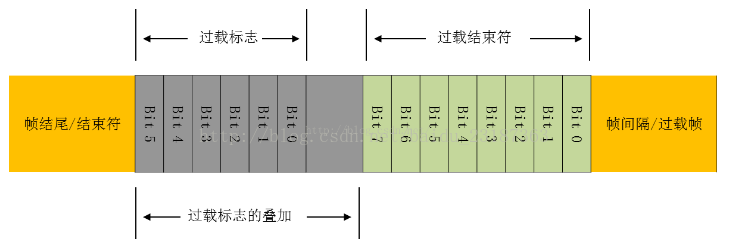 Overload Condition: The receiver requests a delay in the arrival of the next data frame or remote frame; an explicit bit is detected in the first and second bits of the frame interval; if a CAN node samples an explicit bit at the 8th bit of the error delimiter or overload delimiter, it will send an overload frame, and the error counter will not increase.Frame Interval Space: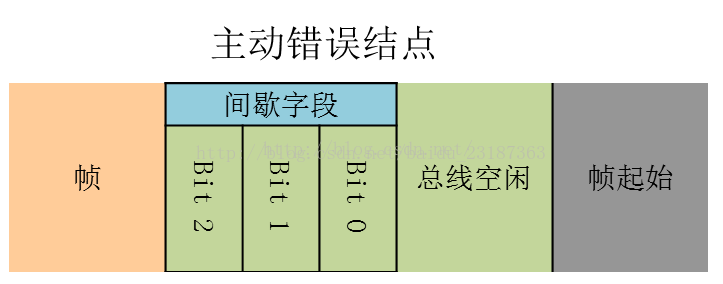
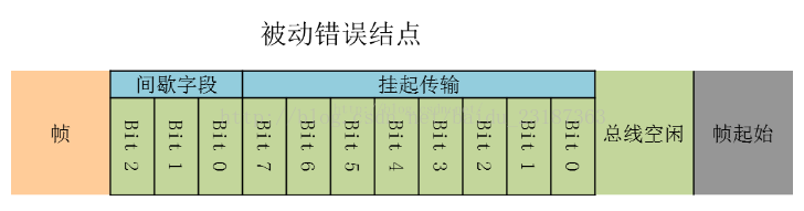 There must be frame interval space before data frames and remote frames. For active error nodes and passive error nodes, the structure of the frame interval space is slightly different. For active error nodes, the frame space consists of a field of 3 explicit bits and bus idle. During the intermittent field, sending data frames and remote frames is not allowed. The length of bus idle is arbitrary, and when there are explicit bits, it is considered the start of the frame. The passive error flag, in addition to the above two parts, has 8 explicit bits of pending transmission after the intermittent field. During the pending transmission phase, passive error nodes cannot send data frames or remote frames.
 Follow our official account, click the “···” in the upper right corner of the homepage to set a star mark, and stay updated on the latest news in intelligent automotive electronics and software.

【Disclaimer】 The article represents the independent views of the author and does not represent the position of Wangcai Automotive Electronics. If there are any issues regarding the content, copyright, etc., please contact Wangcai Automotive Electronics within 30 days of publication for deletion or to discuss copyright usage.