
Source | OCP Official Website
[Insights on Thermal Management] Recently, the OCP official website released a white paper titled “30℃ Coolant– A Durable Roadmap for The Future” authored by a team from META, Vertiv, Samsung, AMD, Intel, and Nvidia, leading participants in the global data center industry. The article focuses on the temperature standards for data center cooling liquids, discussing the significant implications of a 30℃ coolant temperature for the data center and chip industries, the reasons for achieving durability, and the technological pathways to maintain this temperature in the future, providing guidance for the development of AI/ML data center cooling systems.
Therefore, this article aims to explain why both data center operators and chip suppliers prefer to adopt a sustainable coolant temperature standard. The 30℃ coolant provided to chips by data centers offers a target temperature that extends the lifespan of data center investments while also attracting a large user base for chip suppliers. Although standardizing a specific coolant temperature is of great significance to the industry, continuous innovation in various cooling technologies is still required to maintain performance.
01
Introduction
Although liquid cooling technology in computing systems has existed for decades, the demand for higher power density cooling is driving liquid cooling from niche applications to large-scale implementations. AI solutions must evolve rapidly, yet the design, construction, and depreciation cycles of data centers are lengthy. Therefore, it is crucial for data center operators and chip suppliers to agree on the coolant temperature provided to chips. A minimum coolant temperature of 30℃ in the thermal cooling system (TCS) loop provides a valuable operational set point for both parties. This article will explain why 30℃ is the preferred temperature for cooling AI chips in the future and indicate the direction for new technology investments aimed at improving performance.
The 30℃ coolant temperature limit is not intended to hinder the development of various future solutions. While standardizing a coolant temperature of 30℃ or higher is of significant value, we do not intend to restrict the types of technologies used to provide cooling to chips. The industry needs to innovate across various cooling technologies, such as immersion cooling, cold plate technology, and thermal interface materials, to provide ideal solutions. Additionally, there is demand for chip solutions at different coolant temperatures, including those below 30℃. However, the goal of this initiative is to pursue the best cost-performance ratio for chips targeting coolant temperatures above 30℃.
02
Development Trends
In recent years, the application of liquid cooling technology has significantly increased due to the rapid rise in GPU/ASIC power consumption driven by AI/machine learning workloads. Liquid cooling has typically been a “niche” market primarily served by original equipment manufacturers (OEMs) for high-performance computing (HPC) workloads. However, as CPU power has steadily increased from around 100W to over 400W in the past five years, the adoption rate of liquid cooling by cloud service providers (CSPs) and OEMs has also risen sharply.

As shown in the figure, the power growth of GPUs/ASICs is more pronounced than that of CPUs, with power increasing by hundreds of watts almost every year. Chip suppliers like Nvidia, AMD, and Intel have released GPUs with power exceeding 1 kilowatt. Furthermore, cloud service providers such as Microsoft, Google, Amazon, and Meta are designing their own chips for AI/machine learning workloads, which will require liquid cooling technology.
The silicon packaging structure of typical CPUs has remained largely unchanged over several generations, primarily still using monolithic silicon manufacturing. The reduction in chip size (critical feature size) following Moore’s Law has led to improvements in performance and power over time. In contrast, the silicon packaging structure of GPUs has undergone significant changes. The use of chip-on-wafer-on-substrate (CoWoS) 2.5D multi-chip stacking technology has made it possible to design and manufacture more complex silicon packages. Modern data center GPUs rely on this process to tightly package system-on-chip (SoC) with high-bandwidth memory (HBM). This allows different types and numbers of chips to be combined, creating unique and higher-performing GPU packages. Advances in process technology, improvements in packaging assembly techniques, increased processing performance demands, and co-location of memory have largely driven the significant increase in GPU power.
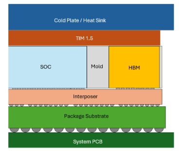
The above figure shows a typical cross-section of a modern GPU stack structure. In this example, the GPU package is connected to the system printed circuit board (PCB) via a ball grid array (BGA). There is a package substrate that supports the component structure, typically with an active intermediary layer chip for power and signal distribution. The SoC and HBM are connected to the intermediary layer chip and filled with materials like silica to fill the gaps created by height differences. Thermal interface materials (commonly referred to as TIM 1.5) are added to facilitate heat transfer between the bare chip and the cold plate. Finally, a cold plate or heatsink is connected to the GPU, completing the assembly of the entire component.
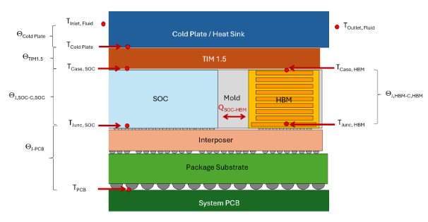
These GPU packaging structures are much more complex than CPUs, presenting unique thermal management challenges. First, different chips or components may require different maximum junction temperatures. Second, different chips may have varying stack heights. Additionally, components may place heat-generating devices in the middle of the stack, with no direct path to the cooling solution. Finally, the close proximity of different chips may lead to thermal crosstalk, which is not present in monolithic silicon. Figure 3 illustrates the different thermal paths contained within a GPU stack. Unlike other CPU-based packaging components, all heat dissipates upwards to the top-mounted cooling solution, with no heat entering the package substrate and system PCB.
Various chips in GPU packaging may be based on different technology nodes, have different functionalities, and require different junction temperature specifications during operation. For example, SoC chips typically operate at a maximum junction temperature of 105℃. Earlier HBM required a lower junction temperature of 85℃ during single refresh operations and 95℃ during double refresh operations. Later HBM increased these two temperatures to 95℃ and 105℃, respectively, to better match the junction temperature requirements of SoCs. When designing cooling solutions, it is essential to consider the differences in junction temperature requirements within the package and plan accordingly.
03
Why Durability Matters
4.1 From the Perspective of Chip Manufacturers
For chip manufacturers, having a data center with a sustainable coolant temperature standard is crucial, as the temperature requirements for chips should not change with each generation of products. The coolant temperature required for the thermal design power of next-generation AI products is much lower than the temperatures currently planned by some data center designers. By establishing a unified coolant standard, chip manufacturers can ensure that their products are adequately cooled during the design phase. Furthermore, a fixed temperature standard provides chip manufacturers with a solid design direction, preventing them from developing two types of products: one that has lower performance but can operate in higher temperature environments, and another that has high performance but cannot be widely used due to cooling limitations imposed by data center operators.
A stable coolant temperature in data centers ensures a broad market for chips designed for liquid cooling environments. While there is demand for chip solutions at different coolant temperatures, including those below 30℃, the goal of this initiative is to pursue the best cost-performance ratio for chips targeting coolant temperatures above 30℃.
4.2 From the Perspective of Data Center Operators
Data center operators have a vested interest in standardizing coolant temperatures for the following reasons: the planning, design, construction, and commissioning of data centers take years, while the development of AI chips is rapidly evolving. Although the industry benefits from the rapid iteration of chips, if the lower coolant temperature required for deploying AI chips changes frequently, new data centers may become outdated before they are completed. Additionally, operating at higher temperature points within the thermal cooling system (TCS) loop is relatively easy and efficient, but adjusting the operating temperature of the TCS loop to below the existing design range after construction is not only costly but also time-consuming. Therefore, determining the lower limit of the TCS loop temperature for data centers is crucial for the long-term viability and investment of data center infrastructure.
Moreover, in hot and warm regions, when the TCS coolant temperature drops from 30℃ to 20℃, the annual energy consumption for cooling data centers can increase significantly. Although 30℃ is not an ideal coolant temperature, it at least provides some options for waste heat reuse. While technically feasible to lower the coolant temperature below 30℃, and there are related products in the industry, the lower efficiency limits its application.
04
Why is 30℃ Optimal for Durability?
Data centers must be designed for specific coolant operating temperatures and flow rates. If the temperature requirements of a generation of IT hardware exceed the design temperature, the coolant temperature can be increased by adjusting the operational set point of the data center, which helps improve efficiency. However, if the temperature requirements are below the design temperature of the data center, expensive and time-consuming modifications to the physical design may be necessary. For instance, lower temperatures may require increasing the capacity of coolers or adopting new types of coolers. Considering the consequences of these changes, it is crucial to set a coolant temperature that does not need to be changed across multiple generations of IT hardware.
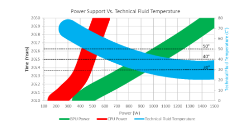
Due to the rapid changes in power and heat dissipation requirements of silicon chips, this is particularly challenging for AI hardware. Figure 6 shows the power trends of GPUs and CPUs and the associated technical fluid temperature requirements. AI hardware drives the demand for liquid cooling, with the growth rate of GPU power far outpacing that of CPU power. The chart illustrates the relevant fluid temperature requirements for GPUs over time, with an asymptotic temperature requirement of 30℃.
We have established 30℃ as the minimum fluid temperature for hardware and data center design, with the line thickness indicating the predicted uncertainty. To maintain 30℃ as a long-term interface specification, investments in advanced silicon packaging and liquid cooling performance are necessary.
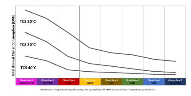
Choosing 30℃ aligns with the common minimum air temperature specifications in large-scale data center designs. Using the same temperature value for both air-cooled and liquid-cooled IT hardware helps the industry maintain the significant improvements in power usage efficiency (PUE) achieved over the past 15 years. Figure 7 shows the relationship between the annual total power consumption of air-cooled natural cooling systems at different technical fluid temperatures and climate zones. The impact of lowering the fluid temperature from 30℃ to 20℃ is evident, as the duration of natural cooling in warmer climate zones decreases throughout the year. Another study indicates that in most climate zones, when the fluid temperature increases from 21℃ to 26℃, the annual power consumption of coolers decreases by 20%; and from 26℃ to 30℃, it decreases by another 20%.
05
How to Maintain Durability in the Future?
The performance of in-rack cooling solutions plays a crucial role in supporting long-term, durable coolant supply temperatures (the technical loop of the facility). This is primarily due to the significant thermal resistance of electronic packaging and cooling solutions. For the latter, functionality can be expanded through existing and future designs. Configuring IT loops as parallel cold plates to eliminate thermal shadows is one such method, but it may require optimizing fin structures and coolant loops to provide performance at lower flow rates. It is generally recommended to design IT cooling solutions to operate long-term at pressures of 50 ~ 75 psig. End users must collaborate with solution providers to ensure that performance is not compromised by such requirements while driving (minimizing) thermal parameters such as substrate thickness, TIM, etc. Relatively new technologies such as flow impact, two-phase cold plates, and higher conductivity fluids should be studied from an end-to-end performance and maintainability perspective to determine viable options for future scalability.
One way to maintain coolant temperature durability in the future is to improve the heat exchanger performance of CDU and indoor air cooling devices by lowering the approach temperature. Lowering the approach temperature allows for higher temperatures in the FWS loop without affecting the TCS coolant temperature or the overall cooling capacity of the data center, thus achieving better thermal management. Higher FWS temperatures also enable air-cooled chillers to operate in natural cooling mode for longer periods, improving the overall efficiency of the data center. This minimizes the use of compressors, limiting their operation to peak periods during the hottest times of the year. This approach combines the high efficiency of natural cooling with the continuous availability of cooling under any conditions, ensuring maximum reliability of the cooling system.
Various methods can be employed to enhance the performance of coils and heat exchangers, depending on the specific type and operating conditions. The most common strategy is to increase the surface area available for heat transfer, which can significantly improve performance. When designing heat exchangers, the cost tends to increase gradually with each improvement in heat exchanger efficiency, necessitating a balance between cost and efficiency. For indoor cooling devices, improved temperature methods include increasing the number of coil rows in indoor air cooling devices and expanding the plate heat exchanger area of the CDU.
The following figure illustrates the thermal resistance contributions of cold plates, TIM, internal packaging, and thermal crosstalk between ASIC and HBM. Figure 16 assumes a typical 2.5D advanced packaging design for AI silicon, which is die-less and features a single-phase cold plate. The data clearly shows where the maximum temperature difference (ΔT) occurs, indicating where the greatest opportunities for improvement lie.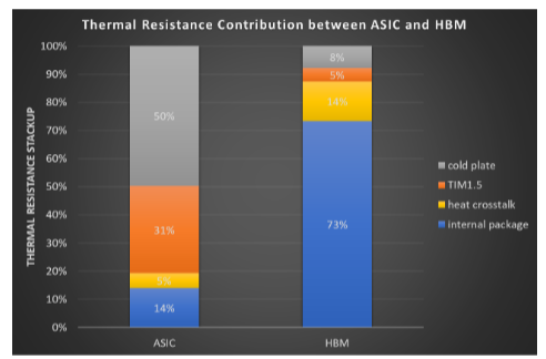 The technology required for AI chips will continue to evolve very rapidly, but the large-scale infrastructure needed to support these technologies requires years of design and construction. Therefore, aligning infrastructure capabilities (such as a 30℃ coolant temperature) with the investments needed to achieve future technological innovations is crucial for building a large, viable AI/ML solution ecosystem in the future.
 ——Recommended Reading——


 ★ Platform Statement
Some materials are sourced from the internet, and copyright belongs to the original authors. The purpose of sharing is solely for industry information dissemination and communication, and does not represent the position of this public account or verify its authenticity. If there are any issues, please contact us for timely handling. Contributions and sharing are welcome!
★ Contact Information
Phone: 13345749273 (WeChat same number)
Email: [email protected]