CPU: STM32F429IGT6
For other STM32 chips or other ARM Cortex-M chips, the solution is generally the same. It is recommended to read this article in full before debugging the issues you encounter.
1. Basic Knowledge
In ARM Cortex-M series processors, there are several system exceptions dedicated to fault handling. The faults in CM3 can be categorized as follows:
(1) Bus faults;
(2) Memory management faults;
(3) Usage faults;
(4) Hard faults;
1.1. Bus Faults
When data is being transmitted on the AHB interface, if an error signal (error response) is returned, a bus fault occurs. The scenarios that can cause this include:
(1) Instruction fetch, commonly referred to as “prefetch abort”;
(2) Data read/write, commonly referred to as “data abort”;
In CM3, the following actions can also trigger a bus fault if the address is incorrect:
(1) The stack PUSH operation at the beginning of interrupt handling. If a bus fault occurs at this time, it is called a “stack entry error”;
(2) The stack POP operation at the end of interrupt handling. If a bus fault occurs at this time, it is called a “stack exit error”;
(3) Reading the vector after the processor starts the interrupt service sequence. This is an extremely rare special case classified as a hard fault.
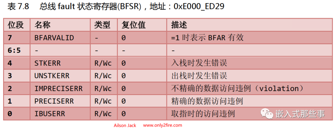
The Bus Fault Status Register (BFSR), address: 0xE000_ED29, the definitions of each bit in BFSR are as follows:
1.2. Memory Management Faults
Memory management faults are often related to the MPU, and their triggers are often due to an access violating the protection specifications set by the MPU. Additionally, certain illegal accesses, such as attempting to fetch instructions from non-executable memory areas, will also trigger a MemManage fault, and in such cases, even without an MPU, a MemManage fault will be triggered. Common triggers for MemManage faults are as follows:
(1) Accessing addresses outside the coverage of all MPU regions;
(2) Accessing empty addresses that do not correspond to any memory;
(3) Writing data to a read-only region;
(4) Accessing addresses that are only allowed at privileged levels under user mode;
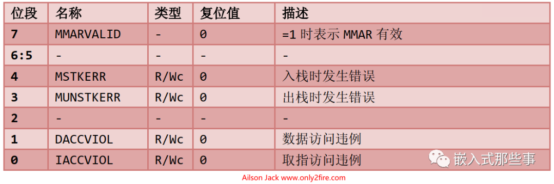
The Memory Management Fault Status Register (MFSR), address: 0xE000_ED28, the definitions of each bit in MFSR are as follows:
1.3. Usage Faults
Usage faults can occur in the following scenarios:
(1) Executing coprocessor instructions. The Cortex-M3 does not support coprocessors, but through the fault exception mechanism, a “software simulation” mechanism can be established to execute a program simulating the functionality of a coprocessor, making it easier to port between other Cortex processors.
(2) Executing undefined instructions. Similarly, the functionality of undefined instructions can also be simulated in software.
(3) Attempting to enter ARM state. Since CM3 does not support ARM state, a usage fault will occur during the switch. Software can use this mechanism to test whether a processor supports ARM state.
(4) Invalid interrupt return (LR contains an invalid/error value);
(5) Using multiple load/store instructions with unaligned addresses.
Additionally, if strict program quality is required, the CM3 can also generate a usage fault when encountering a division by zero or unaligned access. In the NVIC, there are two control bits corresponding to these conditions. By setting these two control bits, they can be activated.
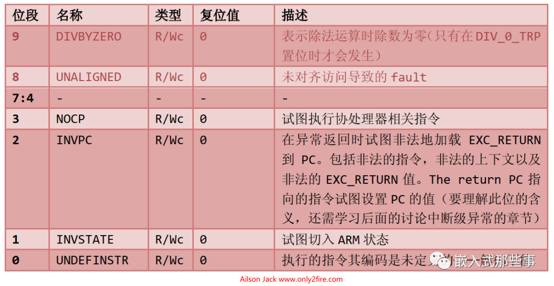
The Usage Fault Status Register (UFSR), address: 0xE000_ED2A, the definitions of each bit in UFSR are as follows:
1.4. Hard Faults
Hard faults are the result of bus faults, memory management faults, and usage faults discussed above. If the service routines for these faults cannot be executed, they escalate to hard faults. Additionally, bus faults that occur when fetching vectors (reading the exception vector table during exception handling) are also treated as hard faults. In the NVIC, there is a hard fault status register (HFSR) that indicates the cause of the hard fault. If it is not caused by vector fetching, the hard fault service routine must check other fault status registers to ultimately determine the source of the escalation.
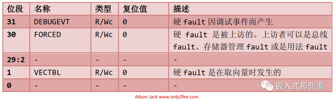
The Hard Fault Status Register (HFSR), address: 0xE000_ED2C, the definitions of each bit in HFSR are as follows:
2. Resolving UsageFault INVPC Set to 1
Recently, while using RTOS to add DMA drivers, a UsageFault occurred during memory-to-device and device-to-memory DMA transfer tests, with INVPC set to 1 in UFSR. Initially, testing DMA transmission alone was fine, but when testing both DMA transmission and reception together, a UsageFault (INVPC set to 1) occurred. This exception is difficult to pinpoint, so I checked the DMA driver and debugged step by step. Ultimately, after checking and modifying the DMA driver, the UsageFault still occurred. I had to analyze why the UsageFault (INVPC set to 1) appeared.
2.1. Causes of UsageFault (INVPC Set to 1)
If the EXC_RETURN in LR is not a valid value (valid values are shown in the figure below, including attempts to return to ARM state), it will cause a usage fault. If the usage fault is disabled, it escalates to a hard fault. At this time, the INVPC bit (bit offset: 2) or the INVSTATE bit (bit offset: 1) in the Usage Fault Status Register (UFSR, address: 0xE000_ED2A) will be set.
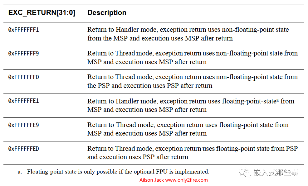
The above is the textual analysis of the occurrence of this exception.
2.2. Resolving UsageFault (INVPC Set to 1)
Since this exception can only occur during the exception response period (as described in section 9.8 of the <
In my case, after starting the DMA test, I entered the UsageFault exception, and my system currently has SysTick, PendSV, DMA1_STREAM5, DMA1_STREAM6, NMI, HardFault, MemFault, BusFault, and UsageFault exceptions and interrupts enabled. Therefore, I set a breakpoint at the start of the DMA test, and when the program runs to the breakpoint at the start of the DMA test, I set breakpoints at the entry of the functions for DMA1_STREAM5, DMA1_STREAM6, NMI, HardFault, MemFault, BusFault, and UsageFault, and also at the return of PendSV, temporarily ignoring SysTick. Then I ran the program at full speed and found that it always stopped at the PendSV exception return breakpoint (due to task switching). In total, it stopped at the PendSV breakpoint about 7 to 8 times before entering the UsageFault.
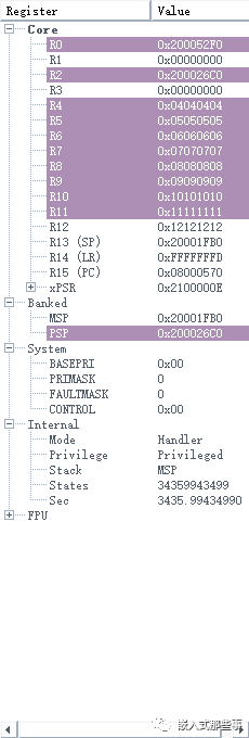
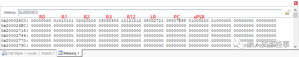
With the above steps laid out, I removed the breakpoints in the interrupts and exceptions, and set a breakpoint at the start of the DMA test again. When the program reached the start of the DMA test, I set breakpoints at the aforementioned interrupt and exception-related locations. Next, I slowly debugged, running at full speed after starting the DMA test, and stepping through to the next step upon exiting the PendSV exception, repeating this 7 to 8 times, and from PendSV, I entered the UsageFault. During these 7 to 8 times, I noticed that the value in the LR register upon exiting PendSV was always 0xFFFFFFFD, which is valid. Upon careful consideration, it might be that there was an issue when the hardware assigned the PC from the stack to the PC upon exiting the exception, leading to the UsageFault. Sure enough, before exiting PendSV, I checked the values of each PSP (0xFFFFFFFD: return to thread mode and use the thread stack), and the registers and PSP stack contents that could exit PendSV normally are shown in the figure below:
The register and PSP stack contents before entering the UsageFault exception are shown in the figure below:
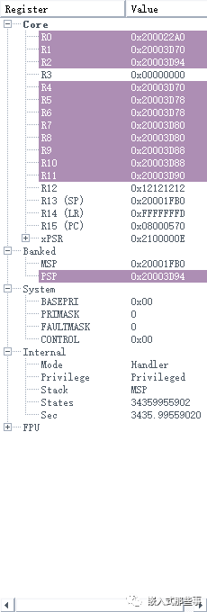
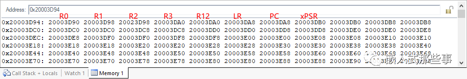
In this case, the content in the stack clearly shows that the PC value of 0x20003D94 in the stack is problematic. The PC address where my program is burned into flash should be 08xxxxxx, but now the PC address in the stack is 0x20003DA8, which is an address in SRAM, indicating that the data in SRAM is not code. The cause of this problem is suspected to be task stack overflow. After I increased the task stack size, the program ran normally, and the world was so beautiful.
3. Debugging Summary
3.1. Summary of the Resolution Process
Actually, the steps in section 2 above are my own debugging process for resolving the issue. Here, I provide a more direct solution. Before running the program, set a breakpoint directly in the UsageFault exception entry function, then run the program at full speed. When the program stops at the breakpoint in the UsageFault exception function, pay attention to the following points:
(1) If LR is a valid value, then based on LR, determine the stack used when exiting the exception, and in the Memory view window, check the values of registers R0, R1, R2, R3, R12, LR, PC, xPSR in the stack. Based on these register values, determine whether a stack overflow caused the exception; if it was not caused by stack overflow, then based on the PC value, jump to the corresponding code in the assembly window to analyze the cause of the exception.
(2) If LR is not a valid value, analyze which parts of your code modified the value of LR, ensuring that the modified value is valid.
3.2. How to Trigger INVPC Set to 1 in UsageFault
(1) When exiting an exception or interrupt, if the value of LR is illegal during the execution of BX LR, it will trigger a UsageFault exception, and INVPC will be set to 1.
(2) When exiting an exception or interrupt, if the value of LR is legal, but the PC value in the stack to be used after exiting the exception is problematic, it may also trigger a UsageFault exception, and INVPC will be set to 1.
Simulating the above two points is relatively easy. Set a breakpoint at the exit of PendSV or other exceptions, and then manually modify the value of LR or the PC value in the stack to trigger the UsageFault exception and set INVPC to 1. Note that when modifying the PC value in the stack, during my testing, setting the PC value to other values may cause other exceptions. It seems that modifying the PC value to an address in the data area of RAM is the only way to trigger this exception. I am not sure why this is the case; it may be because the data area does not have permission to execute code, thus causing the exception. If anyone knows, feel free to leave a comment to explain.
Of course, my knowledge level is limited, and there may be inaccuracies in the explanations regarding exceptions. If there are any errors, please feel free to correct me. Thank you!
If there are any issues in the article, please point them out, as my level is limited.
If this article has helped you, remember to like and follow the author!
Note: Please indicate the source when reprinting. Thank you!